Pneumatic tire

A technology of pneumatic tires and tires, which is applied to tire parts, tire edges, wheels, etc., can solve the problems of reduced bead durability, bead damage, and large impact, and achieve the effect of improving operability

Active Publication Date: 2013-07-24
SUMITOMO RUBBER IND LTD
View PDF4 Cites 4 Cited by
  • Summary
  • Abstract
  • Description
  • Claims
  • Application Information

AI Technical Summary

Problems solved by technology

Under such a large fitting pressure, the impact of the bead portion of the tire when it goes over the hump of the bead seat and is in close contact with the rim flange surface becomes too large, so the bead portion may be damaged and the bead portion may be lowered. durability

Method used


Image

  • Pneumatic tire
  • Pneumatic tire
  • Pneumatic tire

Examples


Embodiment

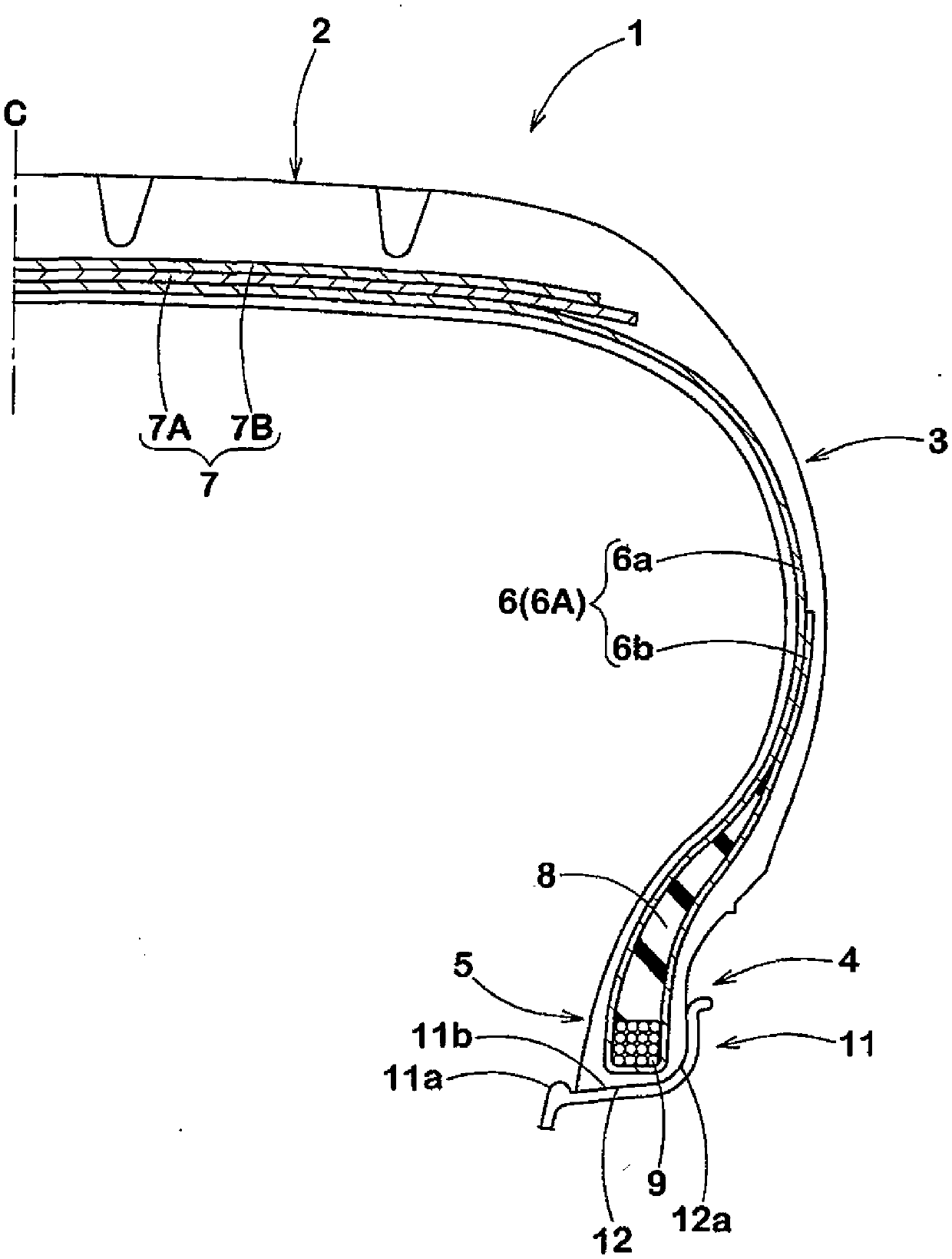
[0067] Formation of specification trial production based on Table 1 figure 1 The size of the basic structure of the pneumatic tire was 175 / 60R15, and the amount of rim misalignment and fitting pressure were tested for each test tire. In addition, the same test was performed using a conventional tire not provided with the above-mentioned second bead wire as a comparative example. The test method is as follows.

[0068]

[0069] Each test tire was installed on a regular rim of 15×6JJ, and after being filled with an internal pressure of 250kPa and left indoors for 72 hours, it was installed on a vehicle, and after a sudden stop at a speed of 50km / h, the tire and rim were measured the amount of misalignment between. The results are represented by an index of 100 for the comparative example, and the smaller the numerical value, the smaller the amount of rim misalignment.

[0070]

[0071] The fitting pressure when each test tire was mounted on the above-mentioned normal rim ...


PUM


Abstract

A pneumatic tire has bead cores provided in bead portions. The bead cores include a first bead wire, and a second bead wire having an elongation alpha, where alpha (%)=DeltaL / L100, L is a length of each of the bead wires under no load, and DeltaL is an elongation amount obtained when a unit load is applied. The elongation alpha of the second bead wire is greater than an elongation of the first bead wire. The number of the second bead wire provided in an innermost side portion in a tire radial direction is at least one.

Description

technical field [0001] The present invention relates to a pneumatic tire in which the fastening force of a bead core is maintained, the fitting pressure is reduced, and the workability at the time of rim assembly and the durability of the bead portion are improved. Background technique [0002] The bead core of a pneumatic tire for passenger cars is formed by continuously winding one or more bead wires in the tire circumferential direction. In addition, various bead cores have been proposed in order to improve various performances of tires. For example, for the purpose of reducing the weight of tires, a bead core in which organic fibers are used for part of the bead wire has been proposed (see Patent Document 1), and for the purpose of absorbing road noise, it has been proposed to provide a vibration-absorbing bead core inside the bead core. Void bead core (see Patent Document 2). [0003] Patent Document 1: Japanese Patent Application Laid-Open No. 7-96720 [0004] Paten...

Claims


Application Information

Patent Timeline
Patent Type & Authority Applications(China)
IPC IPC(8): B60C15/00B60C15/05
CPCB60C2015/048B60C15/04Y10T152/10819B60C15/05
Inventor 青木知荣子
Owner SUMITOMO RUBBER IND LTD
Why Eureka
Try Eureka