Connectors for containers
A technology for containers and connectors, which is applied in packaging, cargo, ship accessories, etc., and can solve the problems of container unloading operations and troubles
- Summary
- Abstract
- Description
- Claims
- Application Information
AI Technical Summary
Problems solved by technology
Method used
Image
Examples
no. 1 example
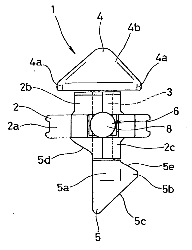
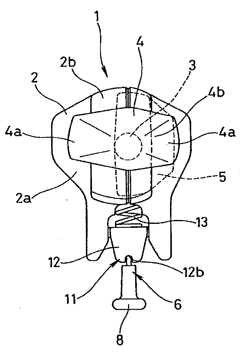
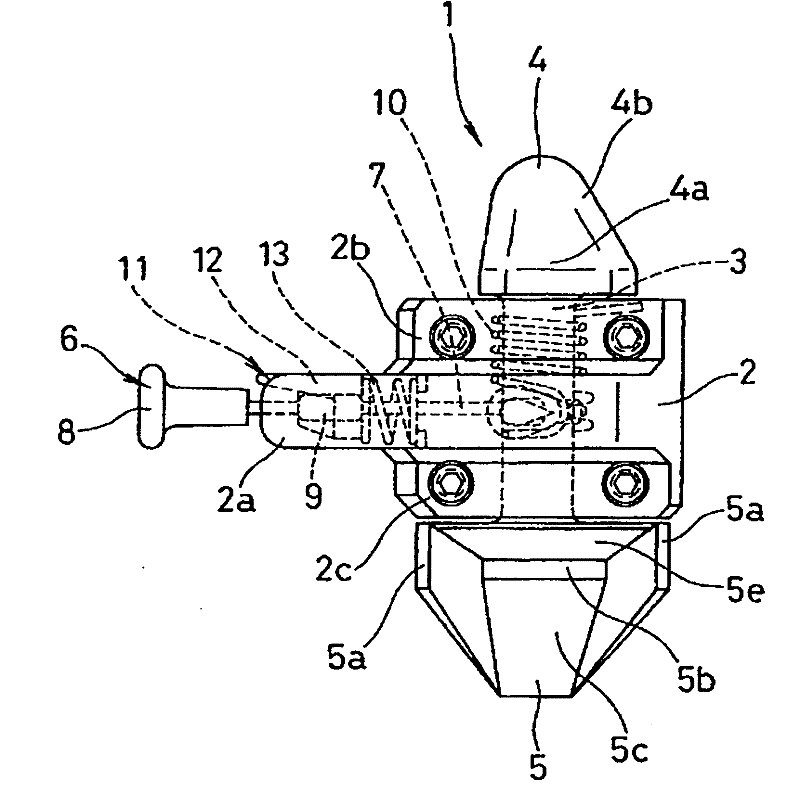
[0095] respectively expressed as: figure 1 is a front view of the connector for the container according to the first embodiment of the present invention, figure 2 is a top view, image 3 is the right side view, Figure 4 is the left view, Figure 5 is a plan view. And, respectively expressed as: Figure 6 to Figure 8 is an explanatory diagram of the rotation position of the upper and lower cones, Figure 9 to Figure 12 It is an explanatory diagram of the operating state of the connector. According to its function and structure, this connecting piece is called container fastening twist lock (twist lock). In addition, the description in the "Example" column below also describes the case of loading and unloading a plurality of containers. Therefore, in the case of securing the container to the deck, in the following descriptions, replace "upper container" with "container", and "the lower corner casting of the upper container" with "the lower corner casting of the containe...
no. 2 example
[0129] In the above-mentioned first embodiment, the initial position of the shaft 3 is that the rotation engagement structure of the upper cone 4 is at the engagement position, the rotation engagement structure of the lower cone 5 is at the engagement release position, and the second engagement Construct the first rotation stop position capable of action ( Figure 6 ), but not limited thereto, the initial motion position of the shaft 3 can also be the second rotation stop position where the rotation engagement structure of the upper side cone 4 and the rotation engagement structure of the lower side cone 5 are all located at the engagement position, for example .
[0130] From this point of view, in this second embodiment, as Figure 15 As shown, when the initial position of the shaft 3 is that the rotation engagement structure of the upper cone 4 and the rotation engagement structure of the lower cone 5 are both located at the second rotation stop position of the engagement ...
no. 3 example
[0134] and, in Figure 17 as well as Figure 18 In the third embodiment shown, the angle θ at which the longitudinal directions of the upper and lower cones 4, 5 intersect in the planar shape 2 It is set to about 110 degrees (based on the long side direction of the upper side cone 4, the long side direction of the lower side cone 5 is displaced about 110 degrees toward the shaft rotation direction (rotating to the left in the figure)), according to the application Inventor's verification, the plane shapes of the upper and lower cones 4, 5 are Figure 17 as well as Figure 18 In the case shown in , when the angle is set in this way, the engagement area (contact area at the time of engagement) of the cones 4, 5 with respect to the corner castings 22, 25 can be set to the maximum. , the angle that is suitable for the longitudinal direction intersecting in the planar shape of upper and lower pyramid 4,5 is set at 100-120 degree (the longitudinal direction of upper side cone 4 i...
PUM
 Abstract
Description
Claims
Application Information
 - R&D
- Intellectual Property
- Life Sciences
- Materials
- Tech Scout
- Unparalleled Data Quality
- Higher Quality Content
- 60% Fewer Hallucinations
Browse by: Latest US Patents, China's latest patents, Technical Efficacy Thesaurus, Application Domain, Technology Topic, Popular Technical Reports.
© 2025 PatSnap. All rights reserved.Legal|Privacy policy|Modern Slavery Act Transparency Statement|Sitemap|About US| Contact US: help@patsnap.com


