See-through pile plate combined type sea inlet road structure

A pile-plate combination and sea road technology, which is applied in infrastructure engineering, roads, roads, etc., can solve the problems of not meeting the requirements of beach oil exploration, lack of operating ships in shallow water areas, and restricting the development of beach and land oil fields. The effect of small maintenance workload, short construction period and strong scour resistance

Inactive Publication Date: 2013-07-24
SINOPEC PETROLEUM ENG DESIGN +1
View PDF6 Cites 4 Cited by
  • Summary
  • Abstract
  • Description
  • Claims
  • Application Information

AI Technical Summary

Problems solved by technology

[0003] 1. Poor water depth adaptability, and there are no suitable operating vessels in shallow water areas
[0004] 2. The requirements for construction machinery and tools are high, the construction process is complicated, and there are certain difficulties in construction
[0005] 3. The project investment is too high and the economic effect is poor
[0006] 4. Relevant industry standards require that all kinds of pipelines are not allowed to be laid on the trestle bridge, which does not meet the requirements of offshore oil exploitation and will seriously restrict the development of offshore oilfields

Method used


Image

  • See-through pile plate combined type sea inlet road structure
  • See-through pile plate combined type sea inlet road structure
  • See-through pile plate combined type sea inlet road structure

Examples


Embodiment Construction

[0026] In order to further disclose the technical solutions of the present invention, the following will be described in detail through examples in conjunction with the accompanying drawings:

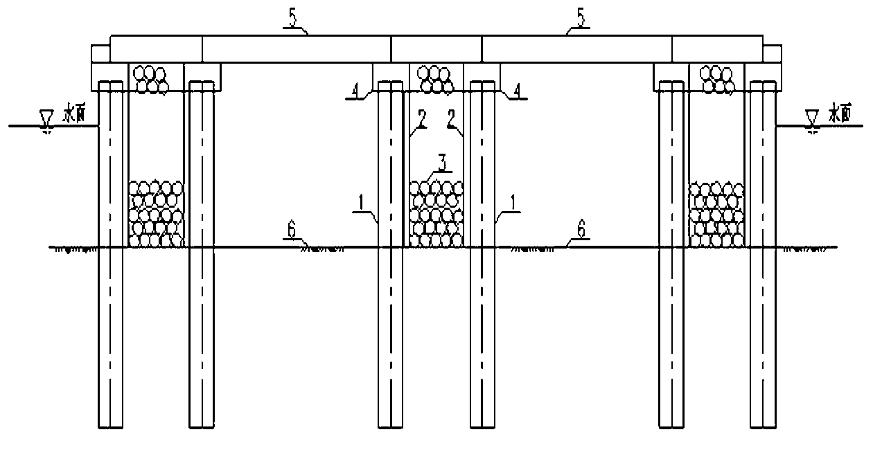
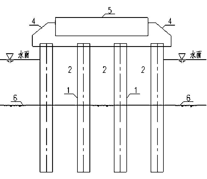
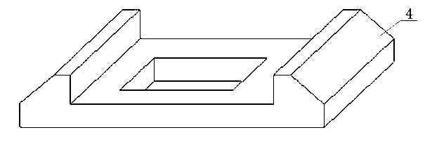
[0027] The present invention comprises reinforced concrete pipe columns, reinforced concrete baffles 2, riprap 3, caps 4 and panels 5, and is characterized in that reinforced concrete pipe piles 1 are arranged side by side laterally, and each row of reinforced concrete pipe piles 1 has at least two pieces, and every two The row is a subgrade support pier, and the reinforced concrete pipe piles 1 of each subgrade support pier are arranged symmetrically. The inner side of each subgrade pier is provided with a reinforced concrete baffle 2 inserted into the seabed mud surface 6 to form a rectangular space filled with riprap 3; the cap 4 between the subgrade pier and the subgrade pier There is a panel 5 on it, and the two ends of the panel 5 are inlaid in the middle of the cap 4, and a water...


PUM


Abstract

The invention provides a see-through pile plate combined type sea inlet road structure which comprises reinforced concrete tubular piles, reinforced concrete baffle plates, ripraps, cushion caps and faceplates. The see-through pile plate combined type sea inlet structure is characterized in that the reinforced concrete tubular piles are transversely arranged with one another side by side, each row of the reinforced concrete tubular piles comprises at least two reinforced concrete tubular piles, every two rows of the reinforced concrete tubular piles are taken as a roadbed buttress, the reinforced concrete tubular piles of each roadbed buttress are symmetrically arranged with one another, the lower end of each reinforced concrete tubular pile is inserted into a mud surface of a sea bottom, the upper end of each reinforced concrete tubular pile is embedded into a circular groove of the bottom surface of the cushion cap, each reinforced concrete baffle plate which is inserted into the mud surface of the sea bottom is arranged on the inner side face of each roadbed buttress to form a rectangular space, and the rectangular space is internally filled with the ripraps; the faceplates are arranged on the cushion caps among the roadbed buttresses, two ends of the faceplates are embedded in the middle of the cushion caps, and water passing culverts are formed between the faceplates and the mud surface of the sea bottom; and the roadbed buttresses are symmetrically designed in the shape of a horizontal line, and the heights of the roadbed buttress which are exposed out of the water surface are on one horizontal line. After the see-through pile plate combined type sea inlet structure is adopted, the sea inlet road quick construction problem and the ground movement reuse problem can be solved.

Description

technical field [0001] The invention relates to a main structure of a sea access road and a sea wall in a beach area, in particular to a structure of a hollow pile-slab combined sea access road. Background technique [0002] With the continuous deepening of China's oil exploration and development, land development has gradually shifted to the beach area, and beach oil development has become the main battlefield of China's oil development. The construction of roads into the sea and beaches and shore platforms or artificial islands is the basic project for oil development in beaches. In addition, the State Oceanic Administration issued the "Opinions on Strengthening the Management of Sea Use for the Construction of Offshore Artificial Islands" (Guo Hai Guan Zi [2007] No. 91) document issued by the State Oceanic Administration in 2008, which requires the construction of land-connected artificial islands. For deep sea areas, island bridges should be used to connect, that is to ...

Claims


Application Information

Patent Timeline
Patent Type & Authority Applications(China)
IPC IPC(8): E01C3/04E02D27/14
Inventor 蒲高军徐志刚王顺华付超廖绍华贾春磊鞠美丽邹积山王岩闫庆华刘波李广庭代彦臣张茂磊刘娜娜刘鹏于彦潘月宇张军孙玉杰邓翊华王晓宁王孝兵耿大勇
Owner SINOPEC PETROLEUM ENG DESIGN
Why Eureka
Try Eureka