
Adjustable cement pouring pipe structure

A technology for pouring pipes and cement, which is applied in the direction of pipes, rigid pipes, building structures, etc. It can solve the problems of easy shaking, inconvenient holding, and affecting the pouring effect, and achieves the effect of convenient use and accurate pouring position

Inactive Publication Date: 2013-07-24
王丽颖
View PDF0 Cites 0 Cited by
  • Summary
  • Abstract
  • Description
  • Claims
  • Application Information

AI Technical Summary

Problems solved by technology

Due to the high pouring height, it is easy to shake during the pouring process, and the pouring pipe is cylindrical, which is inconvenient for the operator to hold, which affects the pouring effect

Method used


Image

  • Adjustable cement pouring pipe structure
  • Adjustable cement pouring pipe structure

Examples


Embodiment Construction

[0009] The specific content of the present invention will be described in detail below in conjunction with the accompanying drawings and specific embodiments.

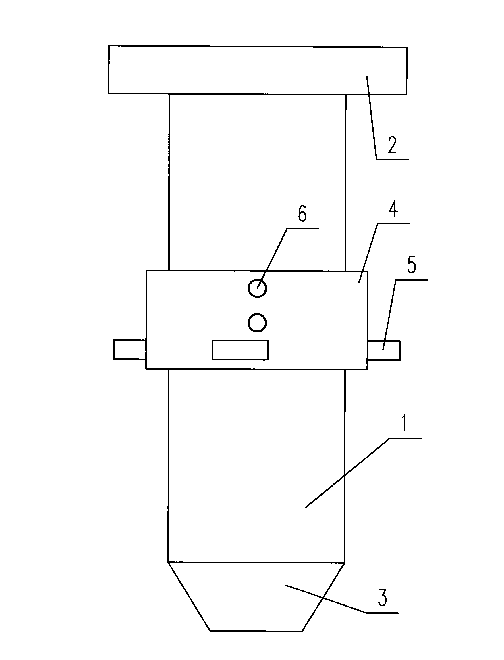
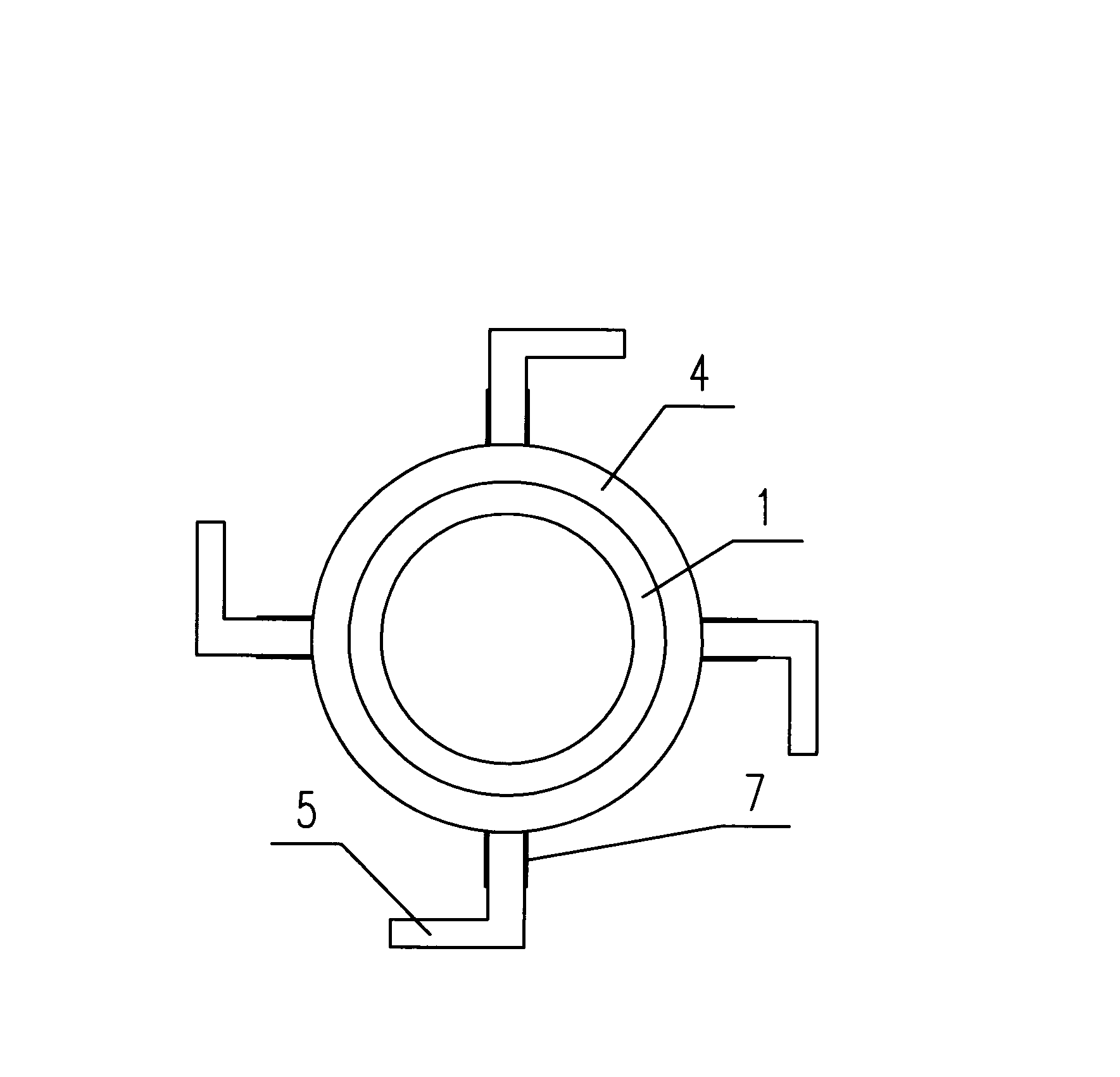
[0010] Such as figure 1 , figure 2 As shown, the adjustable cement pouring pipe structure is characterized in that it includes: pouring pipe 1, a connecting seat 2 is provided at the upper end of pouring pipe 1, and a discharge port 3 is provided at the lower end of pouring pipe 2. In the pouring The outside of the middle part of the pipe 2 is provided with a mounting base 4 and a plurality of handles 5, a plurality of threaded holes 6 are provided on the mounting base 4, and a threaded connection end 7 that cooperates with the threaded holes 6 is provided on the handle 5 .

[0011] When the above-mentioned adjustable cement pouring pipe structure is used, it is connected to the conveying pipe through the connecting seat 2. The cement in the cement tank enters the pouring pipe through the conveying pipe and then pou...


PUM


Abstract

The invention discloses an adjustable cement pouring pipe structure with operation safety. The structure comprises a pouring pipe, wherein the upper end of the pouring pipe is provided with a connecting seat, the lower end of the pouring pipe is provided with a discharge port, the outer side of the middle part of the pouring pipe is provided with a mounting seat and a plurality of handles, the mounting seat is provided with a plurality of thread holes, and each handle is provided with a thread connecting end which is matched with the corresponding thread hole. The structure has the advantages that the deflection of the pouring pipe in the pouring process is avoided by an operation worker through the handles, the accurate pouring position is ensured, the heights of the handles can be adjusted by a user according to requirements in the use process, and more convenience in use is realized.

Description

technical field [0001] The invention relates to a construction machine, in particular to an adjustable cement pouring pipe structure. Background technique [0002] Cement pouring equipment will be used in the construction industry. The existing cement pouring equipment includes: a cement tank and a manipulator set on the tanker. A conveying pipe is arranged on the manipulator. One end of the conveying pipe is connected with the cement tank. The other end of the connecting seat is connected with the upper end of the pouring pipe, and a discharge port is arranged at the lower end of the pouring pipe. When in use, the cement in the cement tank enters the pouring pipe through the conveying pipe and then pours from the discharge port to the position where it needs to be poured. Due to the high pouring height, it is easy to shake during the pouring process, and the pouring pipe is cylindrical, which is inconvenient for operators to hold, which affects the pouring effect. Conten...

Claims


Application Information

Patent Timeline
Patent Type & Authority Applications(China)
IPC IPC(8): E04G21/04F16L9/00
Inventor 王丽颖
Owner 王丽颖
Learn More