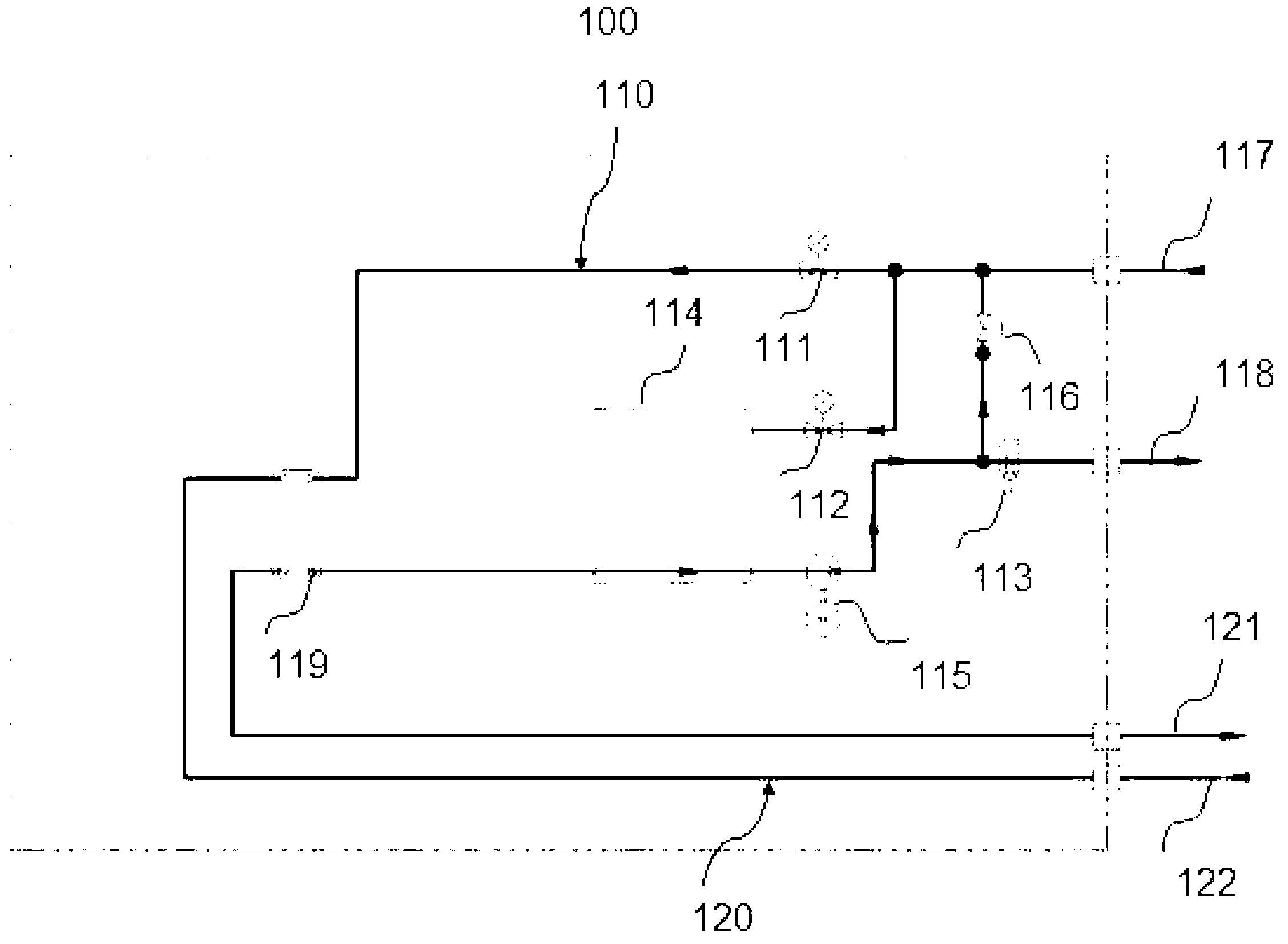
Chiller heat exchanging amount control system

A technology of heat exchange and control system, applied in the field of heat exchange, can solve the problem that it is difficult to control the heat exchange at an appropriate level, etc.

Inactive Publication Date: 2013-07-24
PHST CORP
View PDF5 Cites 6 Cited by
  • Summary
  • Abstract
  • Description
  • Claims
  • Application Information

AI Technical Summary

Problems solved by technology

The disadvantage of the manual valve is that it is necessary to manually adjust the secondary water flow when the primary water temperature is different, while the linear electric valve is difficult to control the heat exchange at an appropriate level even if the secondary water is adjusted to a small amount of water when the primary water temperature is high.

Method used


Image

  • Chiller heat exchanging amount control system

Examples


Embodiment Construction

[0017] In order to make the above objects, features and advantages of the present invention more comprehensible, the present invention will be further described in detail below in conjunction with specific embodiments.

[0018] The term "one embodiment" or "embodiment" here refers to that specific features, structures or characteristics related to the embodiment can be included in at least one implementation of the present invention. The appearances of "in one embodiment" in various places in this specification do not necessarily all refer to the same embodiment, nor do they necessarily refer to a separate or selected embodiment that is mutually exclusive of other embodiments. Furthermore, the order of blocks in a method, flowchart, or functional block diagram representing one or more embodiments does not necessarily refer to any particular order nor constitute a limitation on the invention.

[0019] figure 1 It is a structural schematic diagram of an embodiment of the chille...


PUM


Abstract

The invention discloses a chiller heat exchanging amount control system. A first electromagnetic valve is arranged between a circulating fluid inlet and a first inlet end of a heat exchanger. A second electromagnetic valve is arranged between the circulating fluid inlet and a circulating fluid outlet. The chiller heat exchanging amount control system further comprises a temperature sensor arranged on a circulating fluid channel and used for detecting the temperature of circulating fluid. Based on the circulating fluid temperature detected by the temperature sensor, an opening and closing ratio of each electromagnetic valve is controlled. Part of exchanging heat passing through distributed circulating fluid or gas and cooling water is adjusted, the purpose of wide temperature range control is achieved through ratio adjustment of one or more than two electromagnetic valves, and therefore accurate temperature control in a wide temperature range of the circulating fluid is effectively achieved.

Description

technical field [0001] The invention relates to the field of heat exchange, in particular to a system for precisely controlling the heat exchange amount of an ice water machine. Background technique [0002] The existing cooling water is often used in the temperature control of circulating liquid or gas, which is generally the cooling water (secondary cooling water) made by factory water or cooling water tower for factory equipment, hereinafter referred to as cooling water, and the temperature of this cooling water is mostly fixed (such as 20 degrees Celsius), and the object (equipment) that needs to be controlled often needs another temperature or a temperature that needs to be in a variable temperature range, such as a certain temperature in 20 degrees Celsius to 80 degrees Celsius. A common method is to use another liquid or gas (primary liquid or gas, hereinafter referred to as circulating liquid or circulating gas) and the above cooling water to achieve precise temperat...

Claims


Application Information

Patent Timeline
Patent Type & Authority Applications(China)
IPC IPC(8): F28F27/02
Inventor 王光光
Owner PHST CORP
Why Eureka
Try Eureka