Soft board detection partition position-alignment correction method
A soft board and partition technology, which is applied in the direction of measuring devices, analyzing materials, and material analysis through optical means, can solve problems such as deformation and deviation that cannot be correctly identified, improve detection efficiency and accuracy, eliminate cumulative errors, and save The effect of production costs
- Summary
- Abstract
- Description
- Claims
- Application Information
AI Technical Summary
Problems solved by technology
Method used
Image
Examples
Embodiment 1
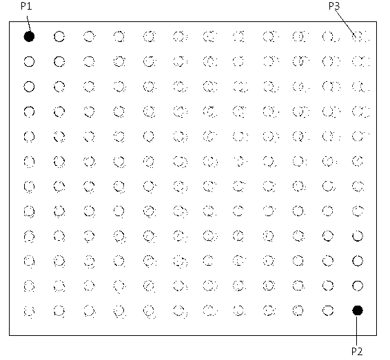
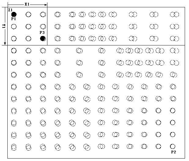
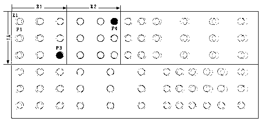
[0041] A soft board detection method for zone alignment detection, such as figure 2 , 3 , 4, 5, and 6, including the following steps:
[0042] a) Use linear ccd equipment combined with stepping motor to scan line by line to obtain soft board image;
[0043] b) Through the recognition algorithm, the openings and lines in the image are converted into graphics;
[0044] c) Set the P1 and P2 two-point graphic marks on the two diagonal vertices of the soft board, and perform the two-point initial alignment through the P1 and P2 graphic marks;
[0045] d) Set the upper limit N of the number of partition graphics, and the distance between the height Y1 of the partition Y direction and the step value X'in the X direction;
[0046] e) Starting from the first graphic position in the upper left corner, the Y direction is fixed to Y1, and the X direction is extended to the right, each time X'distance is extended. When X is extended to X1, the number of graphics in the partition reaches or just exc...
Embodiment 2
[0061] A soft board detection method for zone alignment detection includes the following steps:
[0062] a) Use linear ccd equipment combined with stepping motor to scan line by line to obtain soft board image;
[0063] b) Through the recognition algorithm, the openings and lines in the image are converted into graphics;
[0064] c) Set the P1 and P2 two-point graphic marks on the two diagonal vertices of the soft board, and perform the two-point initial alignment through the P1 and P2 graphic marks;
[0065] d) Set the upper limit N of the number of partition graphics, and the distance between the height Y1 of the partition Y direction and the step value X'in the X direction;
[0066] e) Starting from the first graphic position in the upper left corner, the Y direction is fixed to Y1, and the X direction is extended to the right, each time X'distance is extended. When X is extended to X1, the number of graphics in the partition reaches or just exceeds N , Determine the range Z1 of the...
Embodiment 3
[0075] A soft board detection method for zone alignment detection, such as figure 2 , 3 , 4, 5, and 6, including the following steps:
[0076] a) Use linear ccd equipment combined with stepping motor to scan line by line to obtain soft board image;
[0077] b) Through the recognition algorithm, the openings and lines in the image are converted into graphics;
[0078] c) Set the P1 and P2 two-point graphic marks on the two diagonal vertices of the soft board, and perform the two-point initial alignment through the P1 and P2 graphic marks;
[0079] d) Set the upper limit N of the number of partition graphics, and the distance between the height Y1 of the partition Y direction and the step value X'in the X direction;
[0080] e) Starting from the first graphic position in the upper left corner, the Y direction is fixed to Y1, and the X direction is extended to the right, each time X'distance is extended. When X is extended to X1, the number of graphics in the partition reaches or just exc...
PUM
 Abstract
Description
Claims
Application Information
 - R&D
- Intellectual Property
- Life Sciences
- Materials
- Tech Scout
- Unparalleled Data Quality
- Higher Quality Content
- 60% Fewer Hallucinations
Browse by: Latest US Patents, China's latest patents, Technical Efficacy Thesaurus, Application Domain, Technology Topic, Popular Technical Reports.
© 2025 PatSnap. All rights reserved.Legal|Privacy policy|Modern Slavery Act Transparency Statement|Sitemap|About US| Contact US: help@patsnap.com


