Electric transmission line phase fault single-ended distance measuring method

A transmission line and phase-to-phase short circuit technology, applied in the direction of the fault location, etc., can solve the problems of single-ended fault location results losing reference value, high sampling rate requirements, single-ended fault location results that deviate from the real fault distance, etc.

Active Publication Date: 2013-07-24
STATE GRID CORP OF CHINA +3
View PDF6 Cites 6 Cited by
  • Summary
  • Abstract
  • Description
  • Claims
  • Application Information

AI Technical Summary

Problems solved by technology

The traveling wave method utilizes the transmission properties of fault transient traveling waves to perform single-ended fault location. It has high precision and is not affected by the operation mode and excessive resistance. However, it requires a high sampling rate, requires a special wave recording device, and has high application costs.
The impedance method uses the voltage and current after the fault to calculate the fault loop impedance, and performs single-ended fault distance measurement according to the characteristic that the line length is proportional to the impeda

Method used


Image

  • Electric transmission line phase fault single-ended distance measuring method
  • Electric transmission line phase fault single-ended distance measuring method
  • Electric transmission line phase fault single-ended distance measuring method

Examples


Embodiment Construction

[0014] The technical solution of the present invention will be further described in detail according to the accompanying drawings.

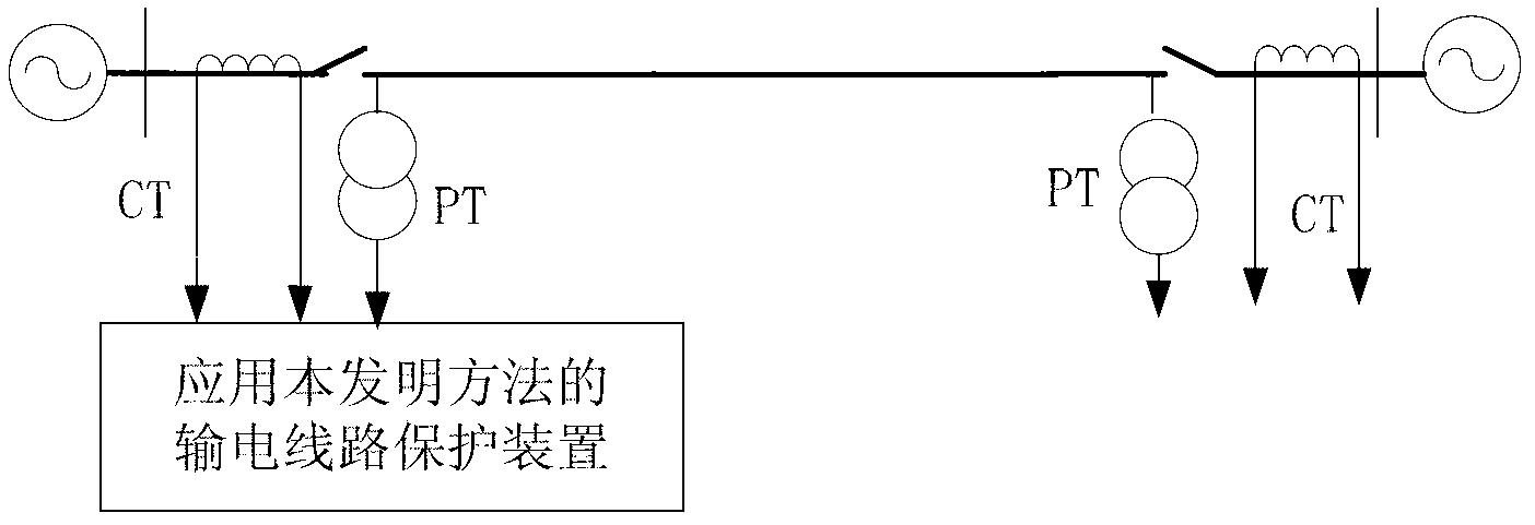
[0015] figure 1 It is a schematic diagram of the line transmission system applying the present invention. figure 1 Among them, PT is a voltage transformer, and CT is a current transformer. The data acquisition system of the protection device samples the voltage waveform of the voltage transformer PT and the current waveform of the current transformer CT at the installation place of the transmission line protection to obtain the instantaneous value of the voltage and current, and uses the instantaneous value of the voltage and current obtained by sampling Calculation of Fault Phase-to-Phase Voltage at Transmission Line Protection Installation by Liye Algorithm , fault current between phases and negative sequence current between fault phases ; Among them, φφ=AB, BC, CA phase.

[0016] The data acquisition system of the protection device wil...


PUM


Abstract

The invention discloses an electric transmission line phase fault single-ended distance measuring method. The electric transmission line phase fault single-ended distance measuring method includes the following steps of working out equivalent resistance through the voltage between fault phases, the current between the fault phases, and the negative-sequence current between the fault phases at the electric transmission line relay location, obtaining the voltage of a phase fault point through the fact that the equivalent resistance is multiplied by the negative-sequence current between the fault phases, working out the real part of a ratio between the voltage of the phase fault point and the voltage drop of an electric transmission line of per unit length, obtaining the additional fault distance caused by a transition resistor, and obtaining the fault distance from the electric transmission line relay location to the phase fault point through the difference between the real part of the ratio between the voltage between fault phases and the voltage drop of the electric transmission line of per unit length and the additional fault distance. The electric transmission line phase fault single-ended distance measuring method solves the problem that the transition resistor influences the precision of electric transmission line phase fault single-ended distance measuring, has high distance measuring precision and is simple in distance measuring principle. In addition, according to the electric transmission line phase fault single-ended distance measuring method, a program is easy to achieve, the fault distance is directly worked out without the need for application of search algorithms, distance measuring is fast, and the instantaneity is strong.

Description

technical field [0001] The invention relates to the technical field of electric power system relay protection, in particular to a single-end distance measuring method for a short-circuit fault between phases of a transmission line. Background technique [0002] The single-end fault location method of transmission lines only uses the electrical quantity at one end of the transmission line for fault location, does not require communication and data synchronization equipment, has low operating costs and stable algorithms, and has been widely used in transmission lines. [0003] Single-ended fault location methods for transmission lines are mainly divided into traveling wave method and impedance method. The traveling wave method utilizes the transmission properties of fault transient traveling waves to perform single-ended fault location. It has high precision and is not affected by the operation mode and excessive resistance. However, it requires a high sampling rate, requires ...

Claims


Application Information

Patent Timeline
IPC IPC(8): G01R31/08
Inventor 曾惠敏林富洪
Owner STATE GRID CORP OF CHINA
Why Eureka
Try Eureka