
Pull-out component unlocking mechanism

An unlocking mechanism and pull-out technology, which is applied in the field of optical module unlocking mechanism, can solve problems such as too many components not suitable for assembly, complex structure, and difficult unlocking, and achieve the effects of easy plugging and unplugging, simple operation, and beautiful appearance

Active Publication Date: 2016-02-24
旭创科技有限公司
View PDF6 Cites 0 Cited by
  • Summary
  • Abstract
  • Description
  • Claims
  • Application Information

AI Technical Summary

Problems solved by technology

[0003] The existing component unlocking mechanism has disadvantages such as relatively complex structure, many components, unsuitable for assembly, and difficult unlocking.

Method used


Image

  • Pull-out component unlocking mechanism
  • Pull-out component unlocking mechanism

Examples


Embodiment Construction

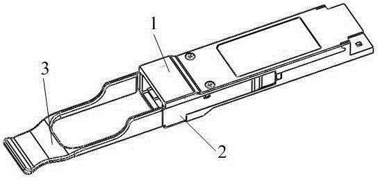
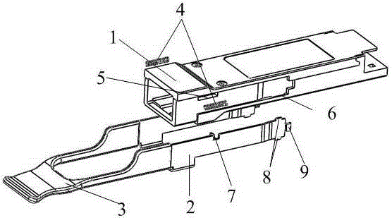
[0014] Such as figure 1 , figure 2 As shown, the pull-type component unlocking mechanism includes a housing 1, a sheet metal part 2, a spring 4 and a flexible pull ring 3. The flexible pull ring 3 is connected with the sheet metal part 2 through injection molding. The front part of the housing 1 A spring groove 5 is provided on both sides, and a spring 4 is respectively installed in the spring groove 5. The middle part of the housing 1 is provided with a limit groove 6 to limit the sliding range of the sheet metal part. The sheet metal part 2 is in a U-shaped structure. The inner side of the middle part of the metal part 2 is provided with a bending shrapnel 7, the bending shrapnel 7 is used to buckle the spring 4 in the component spring groove 5, and the tail of the sheet metal part is provided with an ear-shaped protrusion 8, the function of the ear-shaped protrusion 8 It is to limit the distance that the sheet metal part travels when it moves back and forth. There is a ba...


PUM


Abstract

The invention relates to a drawing assembly unlocking mechanism, wherein a flexible pull ring is connected with a sheet metal part, spring grooves are respectively arranged on both sides on the front part of a shell, each spring groove is provided with a spring, a limiting groove is arranged in the middle part of the shell, the sheet metal part is of a U-shaped structure, a bending elastic piece is arranged inside the middle part of the sheet metal part, a lug bump is arranged at the tail part of the sheet metal part, a buckle bump is arranged at the tail end of the sheet metal part, and the bending elastic piece extends into the spring grooves to buckle the bottom of the springs so as to provide a power for resetting the sheet metal part. The lug bump is arranged in the limiting groove. The flexible pull ring drives the sheet metal part connected therewith to move forward. The buckle bump at the tail end of the sheet metal part also moves forward to distract a locking mechanism, which is used for fixing the shell, on a rack. The assembly and the rack are in an unlocking state and the assembly can be freely taken out. The sheet metal part is reset by means of reaction thrust of the spring after the assembly is taken out. When the assembly is re-inserted into the rack, the locking mechanism of the rack locks the shell. The mechanism is used for assisting to take off the assembly inserted into the rack, and the mechanism is simple and convenient to operate.

Description

technical field [0001] The present invention relates to an optical module unlocking mechanism, in particular to a pull-out component unlocking mechanism, which is used to assist components inserted into a rack to be easily removed from the rack. Background technique [0002] In the field of optical transmission technology, the miniaturization of optical modules can increase the density of network connection ports. In response to this requirement, there are various international standards to define the shape of modules to reduce the size. In order to expand the number of modules in the unit area, it is necessary to arrange the modules in the rack in a stacked manner in order to obtain the maximum number of modules in a limited space, and the corresponding operating space of each module needs to be reduced as much as possible , which requires a more perfect module release and locking structure, so each module is equipped with an unlocking mechanism, which will be very benefici...

Claims


Application Information

Patent Timeline
Patent Type & Authority Patents(China)
IPC IPC(8): G02B6/42
Inventor 王克武王祥忠刘圣
Owner 旭创科技有限公司
Learn More