Optical pickup
A technology for optical pickups and optical discs, which is used in the manufacture of instruments, optical heads, optical recording heads, etc., can solve the problems of increasing and not fully considering the driving force of the focusing coil, and achieves the increase of driving force and excellent assembly workability. Effect
- Summary
- Abstract
- Description
- Claims
- Application Information
AI Technical Summary
Problems solved by technology
Method used
Image


Examples
Embodiment 1
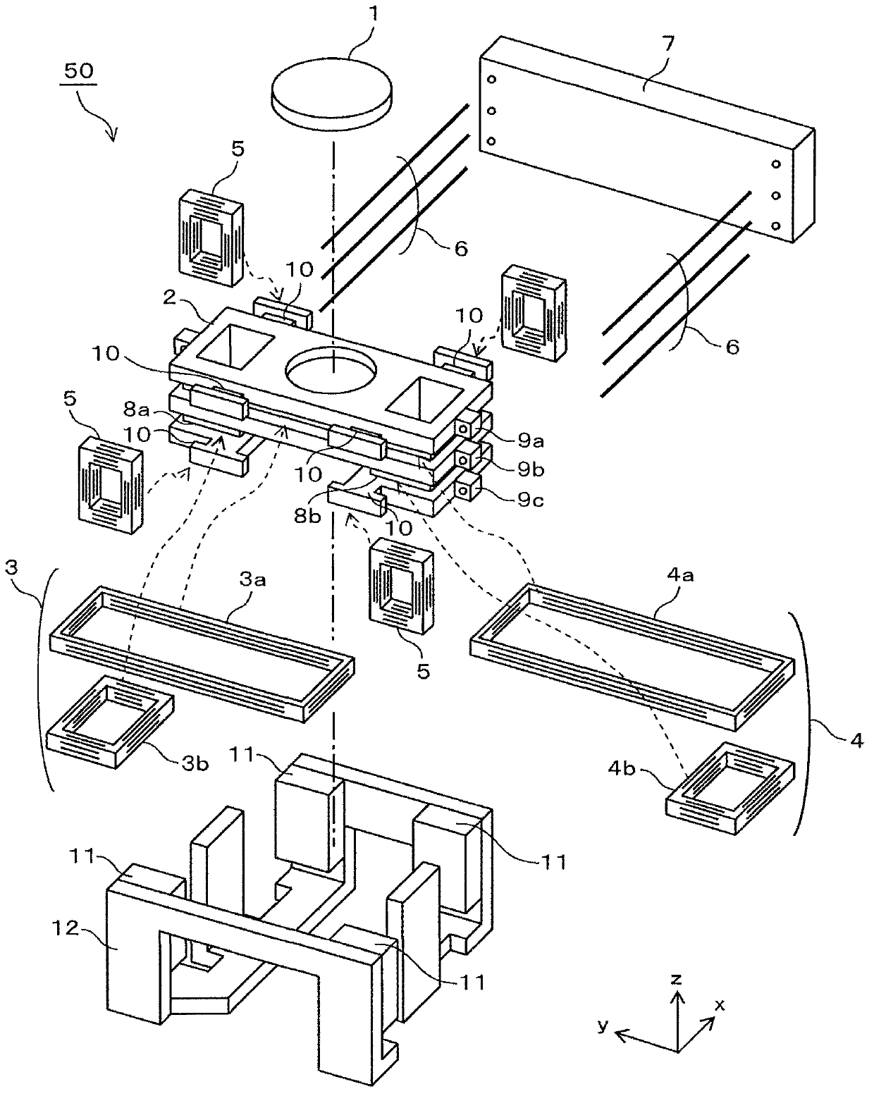
[0049] figure 1 It is an exploded perspective view showing the objective lens drive mechanism 50 of the optical pickup of this embodiment.
[0050] In addition, the z direction in the figure is the optical axis direction of the objective lens 1, and is a focusing direction for bringing the objective lens 1 closer to or farther away from an optical disc (not shown).
[0051] In the z direction, the side closer to the optical disc is set as up, and the side farther from the optical disc is set as down. The y direction is the radial direction of the optical disc, and is a tracking direction for positioning the objective lens 1 with respect to the track of the optical disc. The x direction is a direction perpendicular to both the y direction and the z direction, and is a tangential direction to the optical disc. The direction of rotation around the x-axis is an inclination direction indicating an inclination toward the radial direction of the optical disk.
[0052] exist fig...
Embodiment 2
[0083] Next, use Figure 6 Other embodiments of the present invention will be described.
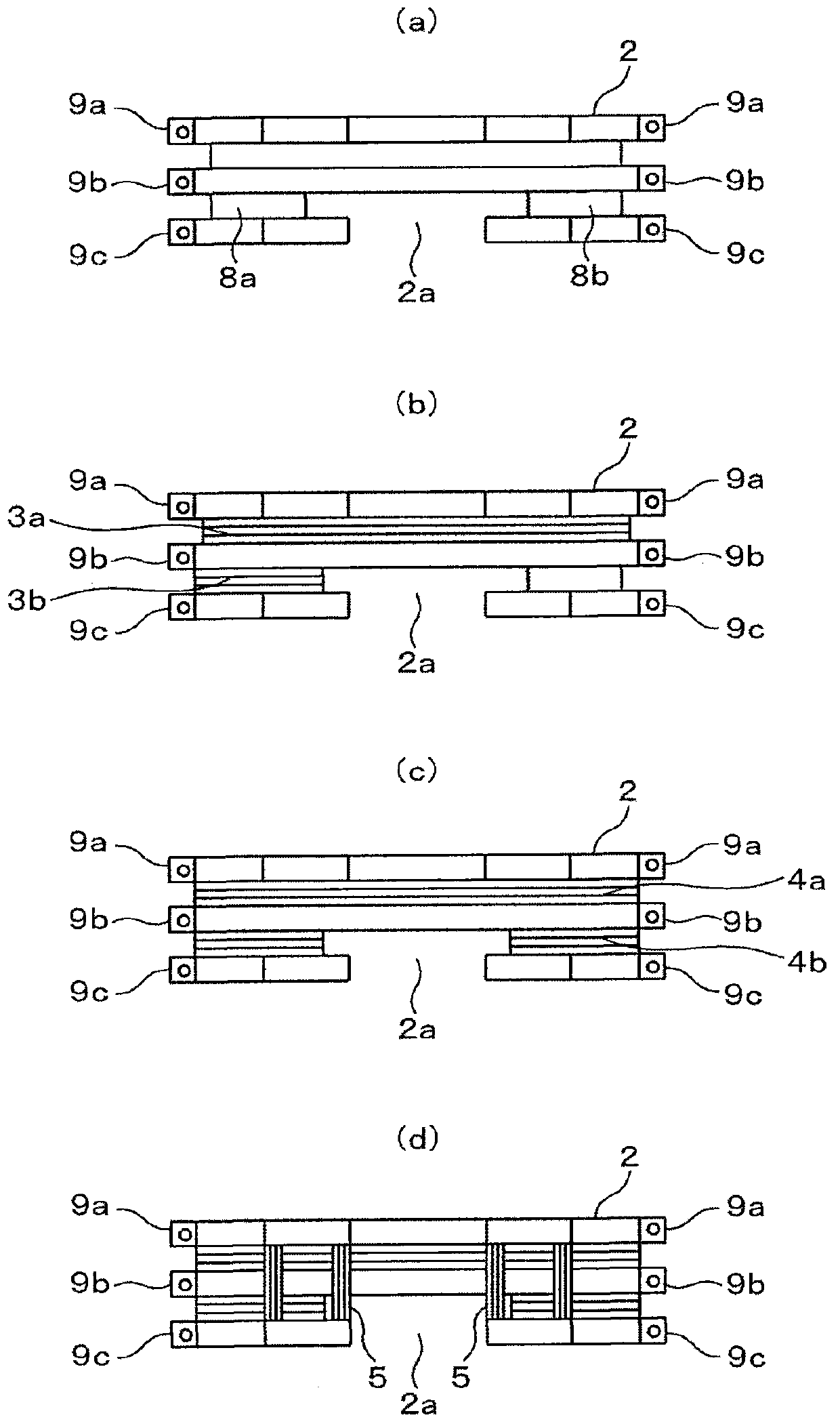
[0084] Figure 6 (a) is a diagram showing the mirror holder 2 and the focusing coil 13 wound around the mirror holder 2 .
[0085] exist Figure 6 In (a), the focus coil 13 consists of the upper side portion 13a of the focus coil wound on the entire circumference of the side surface of the mirror holder 2, and the lower portion of the focus coil wound on the protruding portion 8a on one side of the mirror holder 2. The side portion 13b is configured with the lower side portion 13c of the focusing coil wound around the protruding portion 8b on the other side of the mirror holder 2 .
[0086] The upper side portion 13a of the focus coil is wound between the first support member fixing portion 9a and the second support member fixing portion 9b. The lower side parts 13b and 13c of the focus coil are wound between the second support member fixing part 9b and the third support member fixin...
Embodiment 3
[0093] Next, use Figure 7 represents another embodiment of the present invention.
[0094] Figure 7 (a) is a diagram showing the mirror holder 22 and the focusing coil wound on the mirror holder 22 .
[0095] Figure 7 In (a), the lower portion of the mirror holder 22 has protrusions 28a, 28b on one side and the other side in the radial direction of the optical disc, that is, in the tracking direction. In addition, the mirror holder 22 has a first support member fixing portion 29a, a second support member fixing portion 29a, and a first support member fixing portion 29a in order from the side close to the objective lens 1 along the optical axis direction of the objective lens 1 on each of the two side surfaces on one side and the other side of the tracking direction. The second support member fixing portion 29b and the third support member fixing portion 29c.
[0096] The focus coil is composed of a first focus coil 23 and a second focus coil 24 . The first focusing coi...
PUM
 Abstract
Description
Claims
Application Information
 - R&D
- Intellectual Property
- Life Sciences
- Materials
- Tech Scout
- Unparalleled Data Quality
- Higher Quality Content
- 60% Fewer Hallucinations
Browse by: Latest US Patents, China's latest patents, Technical Efficacy Thesaurus, Application Domain, Technology Topic, Popular Technical Reports.
© 2025 PatSnap. All rights reserved.Legal|Privacy policy|Modern Slavery Act Transparency Statement|Sitemap|About US| Contact US: help@patsnap.com