Display apparatus
A technology for display devices and color filters, applied in static indicators, instruments, diodes, etc., can solve the problem that the shape of the color filter is not specially mentioned, and achieve the effect of suppressing color shift
- Summary
- Abstract
- Description
- Claims
- Application Information
AI Technical Summary
Problems solved by technology
Method used
Image

Examples
no. 1 example )
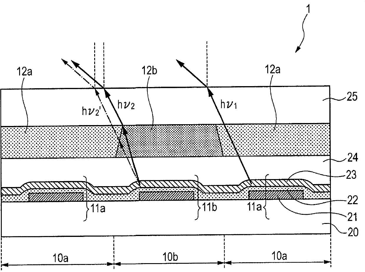
[0026] figure 1 is a schematic sectional view showing the display device according to the first embodiment of the present invention. figure 1 The display device 1 includes a substrate 20, and adjacent two types of pixels disposed on the substrate 20, that is, a first pixel 10a and a second pixel 10b. In addition, two types of pixels ( 10 a and 10 b ) are in close contact with each other and arranged alternately. Note that when viewing the display device from the flat side, including figure 1 The two types of pixels (10a and 10b) within the display device 1 are arranged in a matrix (not shown). also, figure 1The display device 1 is a top emission type display device in which light is extracted from the upper surface side (side opposite to the substrate 20 ) of the organic light emitting elements ( 11 a and 11 b ) formed on the substrate 20 .
[0027] exist figure 1 In the display device 1, the first pixel 10a includes an organic light emitting element (first organic l...
no. 2 example )
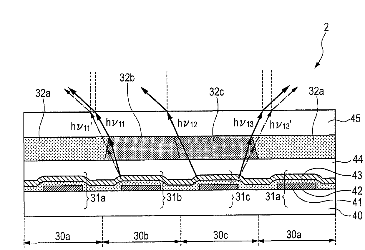
[0056] The above-described embodiment (first embodiment) is a system in which the number of color filter types is two, but in the present invention the number of color filter types is not limited to two, and even when the number is three or more The present invention can also be easily applied in various cases. Furthermore, materials, thicknesses, etc. that are not particularly specified in the second embodiment of the present invention are equivalent to those in the first embodiment.
[0057] figure 2 is a schematic sectional view showing a display device according to a second embodiment of the present invention. figure 2 The display device 2 includes three types of pixels on a substrate 40, that is, a first pixel 30a, a second pixel 30b, and a third pixel 30c. The first pixel 30 a includes an organic light emitting element (first organic light emitting element 31 a ) and a first color filter 32 a. The second pixel 30b includes an organic light emitting element (second o...
example 1)
[0072] Manufactured by figure 1 The display device 1 shown in . Note that the pitch of each pixel included in the display device manufactured in this example was set to 12 μm×6 μm.
[0073] (1) Step of manufacturing the substrate provided with the first electrode
[0074]A pixel circuit (not shown) including TFTs was formed on a silicon substrate, and then an interlayer insulating film made of SiO was formed on the pixel circuit, thereby manufacturing the substrate 20 . Next, a Ti film was formed on the substrate 20 by sputtering. At this time, the thickness of the Ti film was set to 50 nm. Next, the Ti film was patterned for each pixel to form an anode electrode (first electrode 21 ). At this time, the size of the exposed portion of the first electrode 21 was set to 9 μm×4 μm. In this case, the distance between the first electrodes 21 was 2 μm. Next, the substrate 20 on which the first electrode 21 was formed was subjected to ultrasonic cleaning with isopropyl alcohol ...
PUM
 Abstract
Description
Claims
Application Information