Dual Mechanical Port Electromechanical Energy Converter
A technology with dual mechanical ports and electromechanical energy, applied in the direction of electromechanical devices, electrical components, magnetic circuit shape/style/structure, etc., can solve the problems of large volume and low reliability of motors, achieve small volume, reduce equipment maintenance costs, The effect of reducing the size of the system
- Summary
- Abstract
- Description
- Claims
- Application Information
AI Technical Summary
Problems solved by technology
Method used
Image
Examples
specific Embodiment approach 1
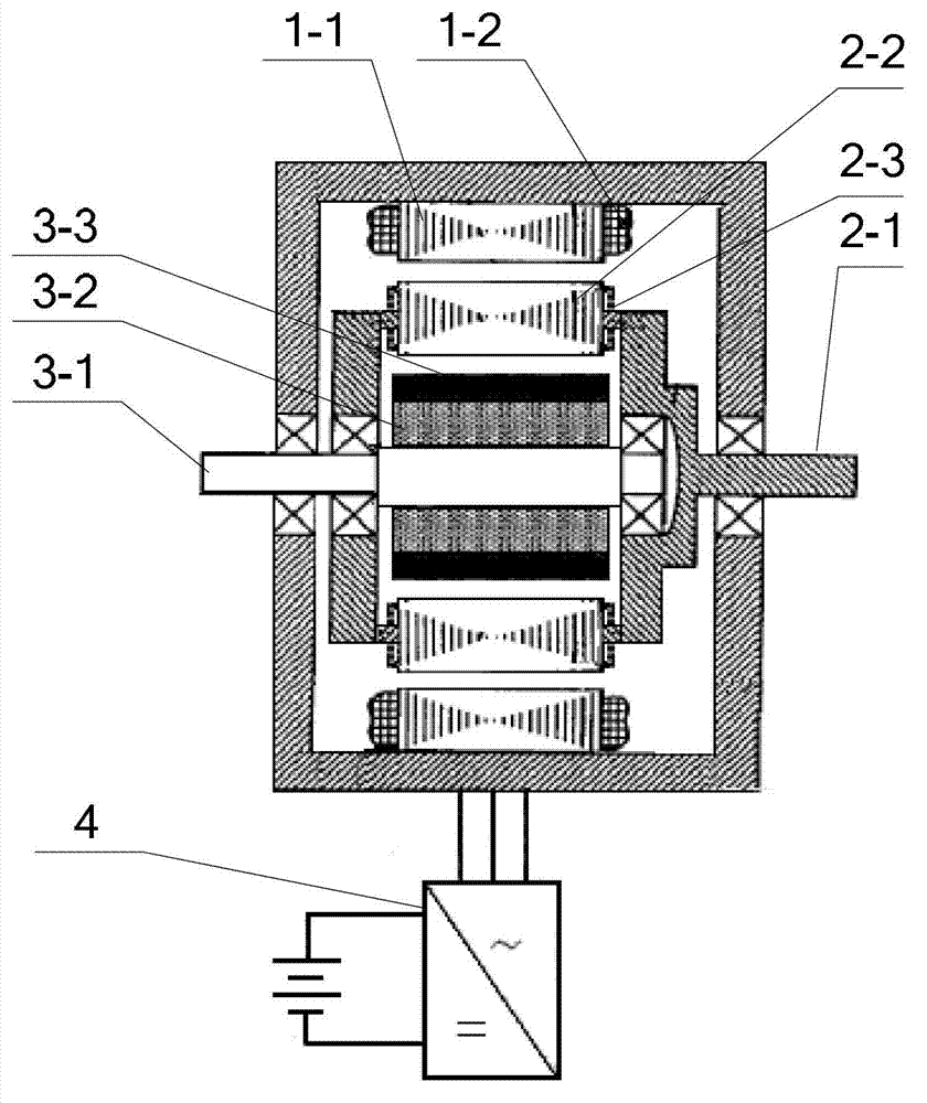
[0068] Specific implementation mode one: the following combination figure 1 Describe this embodiment, the electromechanical energy converter with dual mechanical ports described in this embodiment includes a stator, an outer rotor, an inner rotor and an inverter 4,
[0069] The stator, the outer rotor and the inner rotor are arranged coaxially from outside to inside in sequence, an outer air gap is formed between the stator and the outer rotor, an inner air gap is formed between the outer rotor and the inner rotor, the inner rotor is connected to the inner shaft 3-1, and the outer rotor Connected to the outer shaft 2-1, one end of the stator is connected to the inner shaft 3-1 through a bearing, and the other end of the stator is connected to the outer shaft 2-1 through a bearing;
[0070] The stator includes a stator core 1-1 and a stator multi-phase symmetrical winding 1-2, and the lead wires of the stator multi-phase symmetrical winding 1-2 are connected to the output end ...
specific Embodiment approach 2
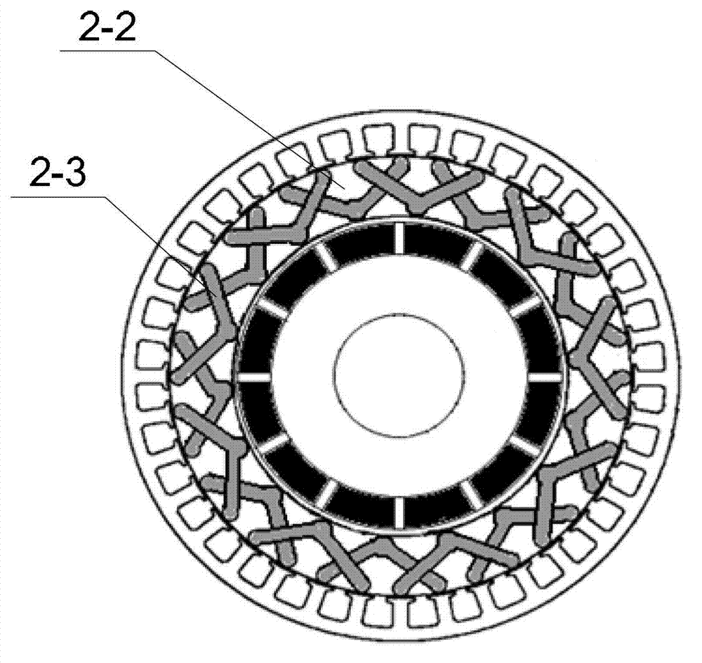
[0075] Specific implementation mode two: the following combination figure 2 , image 3 and Figure 4 Describe this embodiment, this embodiment will further explain Embodiment 1, the outer rotor winding 2-3 is a three-phase short-circuit winding, and the outer rotor winding 2-3 is composed of an outer guide bar, an inner guide bar and an end connection part,
[0076] The inner circumferential side of the outer rotor core 2-2 is provided with a plurality of inner circumferential grooves in the axial direction, and the outer circumferential side of the outer rotor core 2-2 is provided with a plurality of outer circumferential grooves in the axial direction, and the number of the outer circumferential grooves is inner. Twice the number of circumferential grooves, the inner circumferential grooves and the outer circumferential grooves are evenly distributed along the circumferential direction of the outer rotor core 2-2;
[0077] Inner guide bars are embedded in all inner circum...
specific Embodiment approach 3
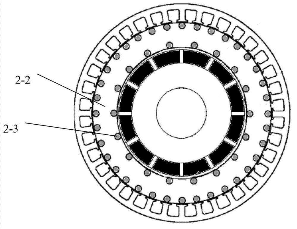
[0081] Specific implementation mode three: the following combination Figure 5 and Figure 6 Describe this embodiment, this embodiment will further explain Embodiment 1, the outer rotor winding 2-3 is a two-phase short-circuit winding, and the outer rotor winding 2-3 is composed of an outer guide bar, an inner guide bar and an end connection part,
[0082] The inner circumferential side of the outer rotor core 2-2 is provided with a plurality of inner circumferential grooves in the axial direction, and the outer circumferential side of the outer rotor core 2-2 is provided with a plurality of outer circumferential grooves in the axial direction, and the number of the outer circumferential grooves is inner. Twice the number of circumferential grooves, the inner circumferential grooves and the outer circumferential grooves are evenly distributed along the circumferential direction of the outer rotor core 2-2;
[0083] Inner guide bars are embedded in all inner circumferential gr...
PUM
 Abstract
Description
Claims
Application Information
 - R&D
- Intellectual Property
- Life Sciences
- Materials
- Tech Scout
- Unparalleled Data Quality
- Higher Quality Content
- 60% Fewer Hallucinations
Browse by: Latest US Patents, China's latest patents, Technical Efficacy Thesaurus, Application Domain, Technology Topic, Popular Technical Reports.
© 2025 PatSnap. All rights reserved.Legal|Privacy policy|Modern Slavery Act Transparency Statement|Sitemap|About US| Contact US: help@patsnap.com


