Display device and television receiver

A display device and display surface technology, which can be applied to TVs, color TVs, identification devices, etc., can solve the problem of increasing the number of assembly operations, and achieve the effects of no deterioration in installation operability, low cost, and vibration suppression.

Inactive Publication Date: 2013-07-24
SHARP KK
View PDF8 Cites 6 Cited by
  • Summary
  • Abstract
  • Description
  • Claims
  • Application Information

AI Technical Summary

Problems solved by technology

In conventional display devices, screws are used to fix the panel module and the front case, which causes a problem that the number of assembly operations increases.

Method used


Image

  • Display device and television receiver
  • Display device and television receiver
  • Display device and television receiver

Examples


Deformed example 1

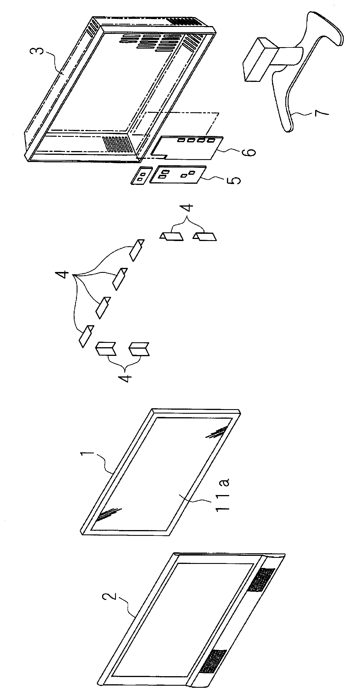
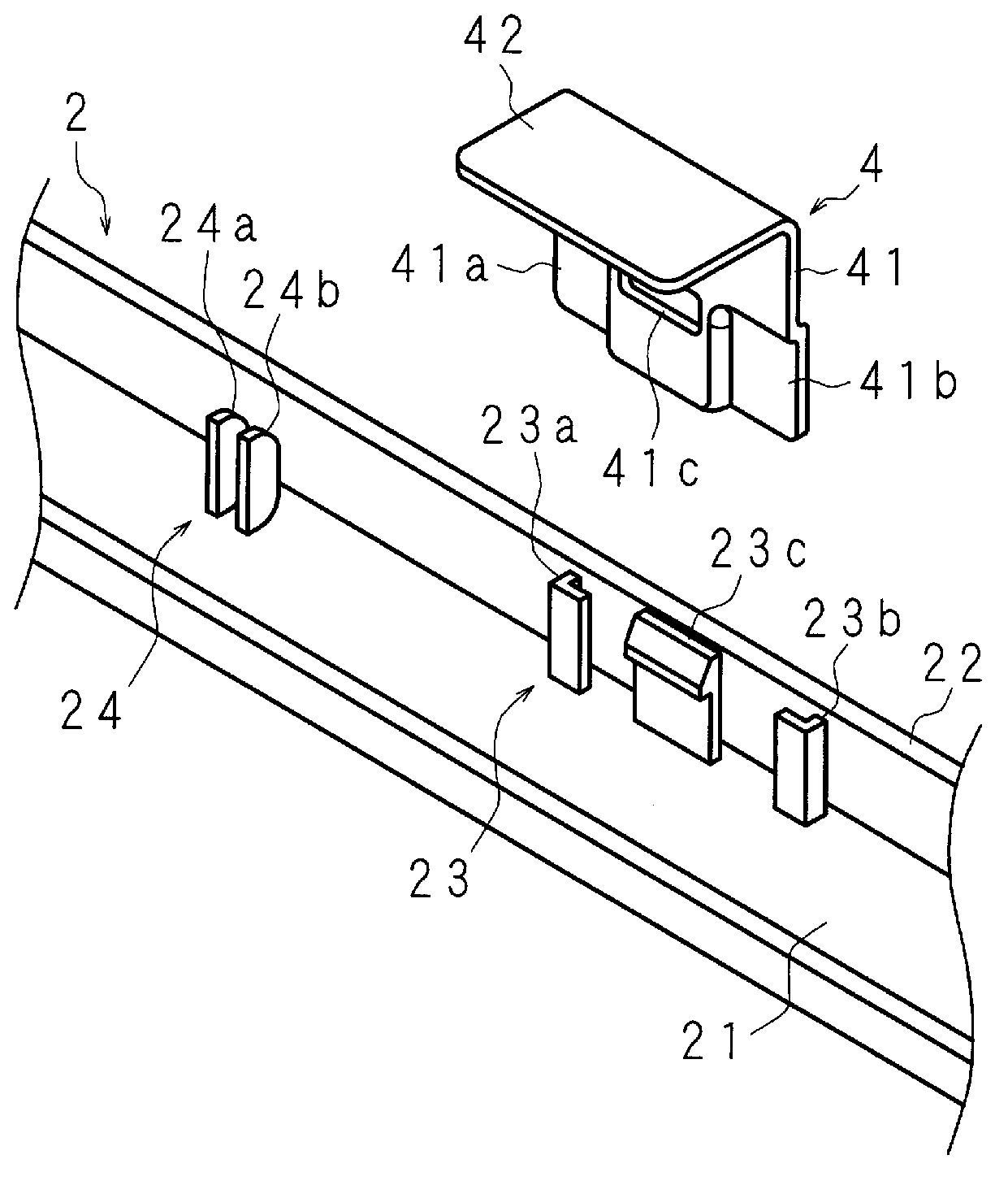
[0083] Figure 9 It is an exploded perspective view showing main parts on the back side in a state where the front case 102 is attached to the panel module 1 by using the L-shaped fixing member 104 according to Modification 1, Figure 10 It is an exploded perspective view showing main parts on the back side in a state where the L-shaped fixing member 104 according to Modification 1 is engaged with the flexible claw portion 123c, Figure 11 It is an exploded rear view showing main parts on the rear side in a state where the front case 102 is attached to the panel module 1 using the L-shaped fixing member 104 according to Modification 1. FIG. Figure 12 is a perspective view showing the main part of the front case 102, Figure 13 It is a rear view and a side view showing the main part of the front case 102, Figure 14 is a perspective view of the L-shaped fixing member 104, Figure 15 It is a six-sided view of the L-shaped fixing member 104 .

[0084] As in the embodiment, a...

Deformed example 2

[0105] Since the display device according to Modification 2 differs from the embodiment and Modification 1 only in the structure of the flexible claw portion, the difference will be mainly described below. The flexible claws are used to prevent the L-shaped fixing member from coming off, and the flexible claws hardly apply force to the L-shaped fixing member after it is attached to the front case of the panel module by the L-shaped fixing member. Therefore, looseness occurs between the L-shaped fixing member and the panel module in the front-rear direction of the display device, and vibration due to sound or the like occurs. As a countermeasure against chattering, methods such as attaching a non-woven fabric Himeron (Japanese: ヒメロン) to the contact portion between the L-shaped fixing member and the panel module have been considered, but there are problems of reduced operability and increased number of components. The display device according to Modification 2 can avoid a decrea...

Deformed example 3

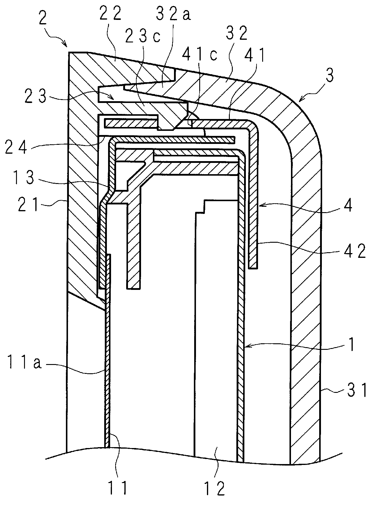
[0113] Figure 20 It is an enlarged side cross-sectional view showing a main part of a display device according to Modification 3. FIG. The display device according to Modification 3 includes the panel module 1 , the front case 302 and the back case 303 as in the embodiment. The structure of the rear case 303 is the same as that of the first embodiment or the first modification, and includes a dish-shaped covering part 331 covering the rear side of the panel module 1 and a rear tube part 332 connected to the periphery of the dish-shaped covering part 331 .

[0114] In addition, the L-shaped fixing member 304 is L-shaped like Modification 1, and includes: an engaging plate 341 having a hole 341c engaged by a flexible claw 323c; and an abutting plate 342, which The connecting plate 342 abuts against the rear surface of the above-mentioned panel module 1 . Both the engaging plate 341 and the abutting plate 342 are substantially rectangular, and the long sides are connected to e...


PUM


Abstract

Provided is a display device with which it is possible to anchor a panel module in a front cabinet without using a screw, and with which it is possible moreover to easily remove the panel module from the front cabinet when carrying out maintenance. A display device comprises: a panel module (1) further comprising a display screen (11a) at the front side thereof; a front cabinet (2) which encases the periphery part of the panel module (1); and a back cabinet (3) which covers the rear side of the panel module (1). The display device further comprises: a flexible hook part (23c) which protrudes from the interior face of the front cabinet (2) toward the back cabinet (3); and an L-shaped anchoring part (4), having an L-shape, a latch plate (41) with a hole part (41c) whereon the flexible hook part (23c) latches, and a contact plate (42) which makes contact with the rear face of the panel module (1). The L-shaped anchoring part anchors the front cabinet (2) to the panel module (1).

Description

technical field [0001] The present invention relates to a display device and a television receiver, comprising: a panel module having a display surface on the front side, a front case surrounding the peripheral portion of the panel module, and a back case covering the rear side of the panel module. Background technique [0002] A display device such as a television receiver includes: a panel module having a display surface for displaying video on the front side; a front case which surrounds the peripheral portion of the panel module; and a back case which covers the above-mentioned panel module. rear side. In the conventional display device, the panel module and the front case are fixed by screws, which causes a problem that the number of assembly steps increases. [0003] Patent Document 1 discloses a display device that solves the above problems. The display device according to Patent Document 1 includes a plurality of flexible hooks protruding rearward from the outer ed...

Claims


Application Information

Patent Timeline
Patent Type & Authority Applications(China)
IPC IPC(8): G09F9/00G02F1/1333H04N5/64
CPCH04N5/64G09F9/00G02F2201/465G02F1/1309H05K5/0221G02F1/133308
Inventor 诹访健一木口大作西井武史竹内淳一江畑裕介长谷川仁
Owner SHARP KK
Why Eureka
Try Eureka