Ferrite three-stage three-phase permanent magnet motor

A permanent magnet motor, three-stage technology, applied to synchronous motors with stationary armatures and rotating magnets, magnetic circuits, electrical components, etc., can solve the problems of large copper consumption and high cost, and achieve material minimization and high The effect of operating speed and air gap minimization

Active Publication Date: 2016-06-01
ZHEJIANG BOWISE TECH DEV
View PDF5 Cites 0 Cited by
  • Summary
  • Abstract
  • Description
  • Claims
  • Application Information

AI Technical Summary

Problems solved by technology

[0005] In view of the above defects of the existing permanent magnet motor, the present invention solves the problems of large copper consumption and high cost of the traditional permanent magnet motor

Method used


Image

  • Ferrite three-stage three-phase permanent magnet motor
  • Ferrite three-stage three-phase permanent magnet motor
  • Ferrite three-stage three-phase permanent magnet motor

Examples


Embodiment Construction

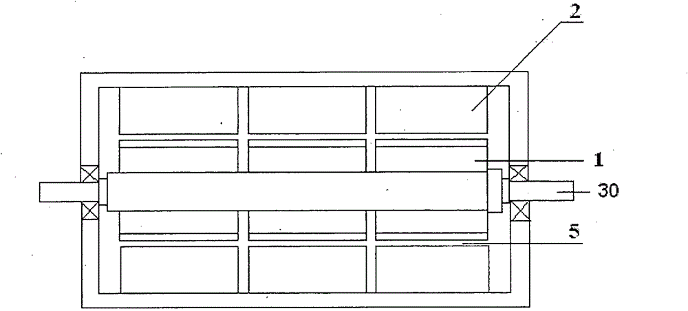
[0023] Such as figure 1 Shown is a preferred embodiment of the present invention, the main components of this ferrite three-stage three-phase permanent magnet motor include a rotor 1, a stator 2, a rotating shaft 30, etc., and the physical air gap 5 between the rotor 1 and the stator 2 is 0.5~3.0mm. The stator core is a three-stage structure made of soft ferrite, and the A, B, and C three-phase windings each occupy the first, second, and third sections;

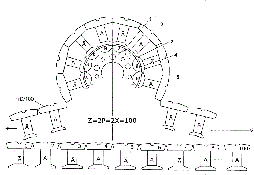
[0024] In the following embodiments, X=50 is taken, so Z=2P=2X=100; during specific implementation, any value among X=21, 22, 23, . . . 100 can also be taken. Such as figure 2 As shown, in the following descriptions, phase A is taken as an example. The first section of the stator core is composed of 100 teeth 40 made of independent soft ferrite, so the number of slots of the stator Z=100.

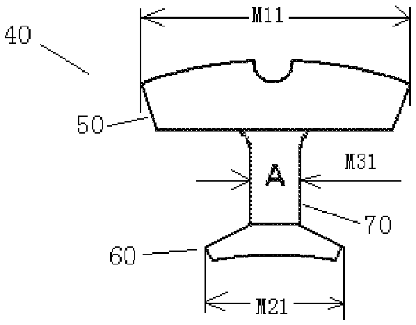
[0025] Such as image 3 and Figure 4 As shown, the relationship between the width M11 of the outer circle end 50 of each tooth 40,...


PUM


Abstract

A ferrite three-section three-phase permanent magnet motor is provided, in which a stator iron core has a three-section structure made of soft magnetic ferrite, and each of the three phase windings A,B,C occupies one section; the slot number of the stator iron core is Z, the number of magnetic poles of the rotor is 2P, Z=2P=2X, in which X=21,22,23,...100; a plurality of slots used for embedding winding are formed in front and back, on the left and right of each tooth; each phase has 2X concentrated windings which are circularly arranged in accordance with the order of A-> / A; the phase B and phase C have the same structure and the space phases of the three phase A, B, C stator iron cores differ from each other at 120º electric angle. The motor has advantages of small winding end, small positioning torque, less copper loss and iron loss et al.

Description

technical field [0001] The present invention relates to a permanent magnet motor, and more particularly, to a ferrite three-stage three-phase permanent magnet motor, which is suitable for refrigerators, air conditioners and high-speed drive applications. Background technique [0002] The stator core of the permanent magnet motor is generally made of silicon steel sheets, and the rotor is generally made of rare earth permanent magnets, such as NdFeB permanent magnets. Silicon steel sheets and rare earth permanent magnet materials are becoming more and more scarce and more expensive. In order to change this situation, many efforts have been made. [0003] One of the improvements is to use a motor without a stator core. This type of design will inevitably increase the amount of permanent magnets. [0004] Another improvement plan is to use hard ferrite magnets, which can avoid the use of rare earth permanent magnet materials, but it will inevitably lead to a lower magnetic lo...

Claims


Application Information

Patent Timeline
Patent Type & Authority Patents(China)
IPC IPC(8): H02K1/14
CPCH02K1/148H02K21/16
Inventor 杜坤梅曹立明
Owner ZHEJIANG BOWISE TECH DEV
Why Eureka
Try Eureka