Rotor and rotating electric machine

a technology of rotating electric machines and rotors, which is applied in the direction of dynamo-electric machines, magnetic circuit rotating parts, and shape/form/construction of magnetic circuits, etc., can solve the problems of high manufacturing cost and increase in maintenance cost of dies, and the fit between protruding protruding recesses is close to interference fit, so as to reduce time and effort for performing assembly process, facilitate the assembly process of the rotor core, and high roundness

Active Publication Date: 2016-03-31
DENSO CORP
View PDF7 Cites 7 Cited by
  • Summary
  • Abstract
  • Description
  • Claims
  • Application Information

AI Technical Summary

Benefits of technology

[0010]With the above configuration, there are the gap formed between each circumferentially adjacent pair of the core segments and the clearance provided between the through-holes of the rotor core and the fixing members. With the gap and the clearance, the tolerances in forming the core segments and the deviations in assembling the core segments and in fixing the rotor core to the fixed member by the fixing members can be absorbed. Therefore, it is possible to easily perform the assembly process of the rotor core by arranging and stacking the core segments along a jig whose coaxiality is ensured. Consequently, it is possible to reduce the time and effort for performing the assembly process.
[0011]Moreover, with the gap and the clearance, it is possible to secure high roundness and thus high coaxiality of the rotor core only by assembling the core segments along the shape of the jig. Consequently, with the high coaxiality of the rotor core (or the rotor), it is possible to minimize the air gap between the rotor and a stator to be disposed in radial opposition to the rotor.
[0012]Furthermore, with the clearance less than the gap, when any circumferentially adjacent pair of the core segments are both deviated toward the gap therebetween, the circumferential end surfaces of the pair of the core segments are prevented from making contact with each other. Consequently, it is possible to prevent the core segments from being deformed due to contact therebetween, thereby making it possible to accurately assemble the core segments.
[0013]In addition, with the above configuration, it is possible to improve the material yield of the rotor core in comparison with the case of forming a rotor core into one piece by, for example, blanking. Moreover, it is also possible to reduce the sizes of dies used for forming the core segments. Consequently, it is possible to reduce the manufacturing cost of the rotor.

Problems solved by technology

Therefore, increasing the roundness of the rotor core will result in an increase in the manufacturing cost as well as an increase in the maintenance cost of dies.
Moreover, when the core segments are formed at high accuracy, the fit between the protrusions and the recesses is close to interference fit.
Therefore, it is not easy to perform the assembly process of the rotor core.
On the other hand, when the core segments are formed at low accuracy, the coaxiality of the rotor core with a stator is low.
Therefore, it is inevitable to increase the size of an air gap provided between the rotor core and the stator, thus lowering the performance of the rotating electric machine.

Method used


Image

  • Rotor and rotating electric machine
  • Rotor and rotating electric machine
  • Rotor and rotating electric machine

Examples


first embodiment

[0043]A first exemplary embodiment will be described hereinafter with reference to FIGS. 1-14.

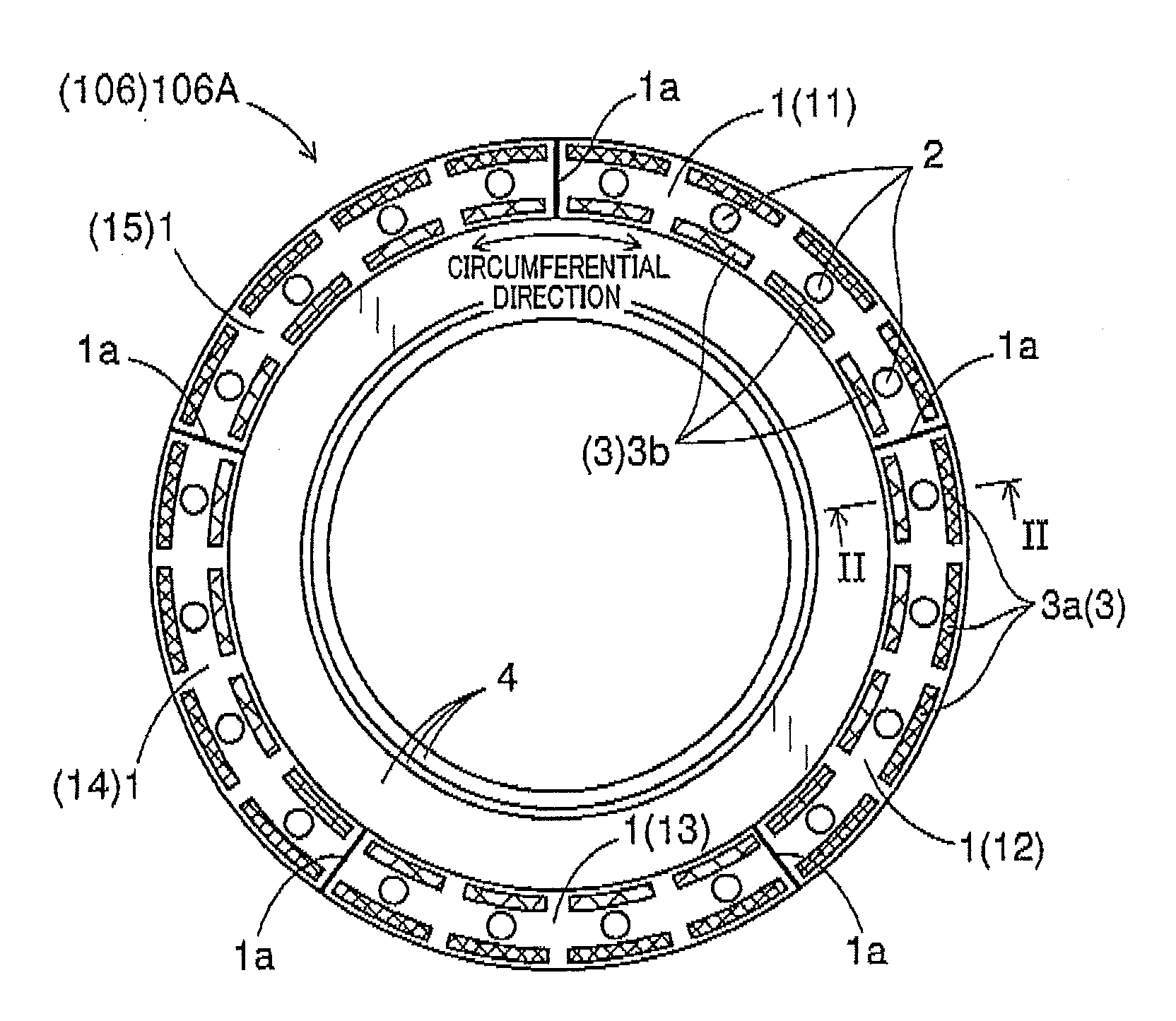
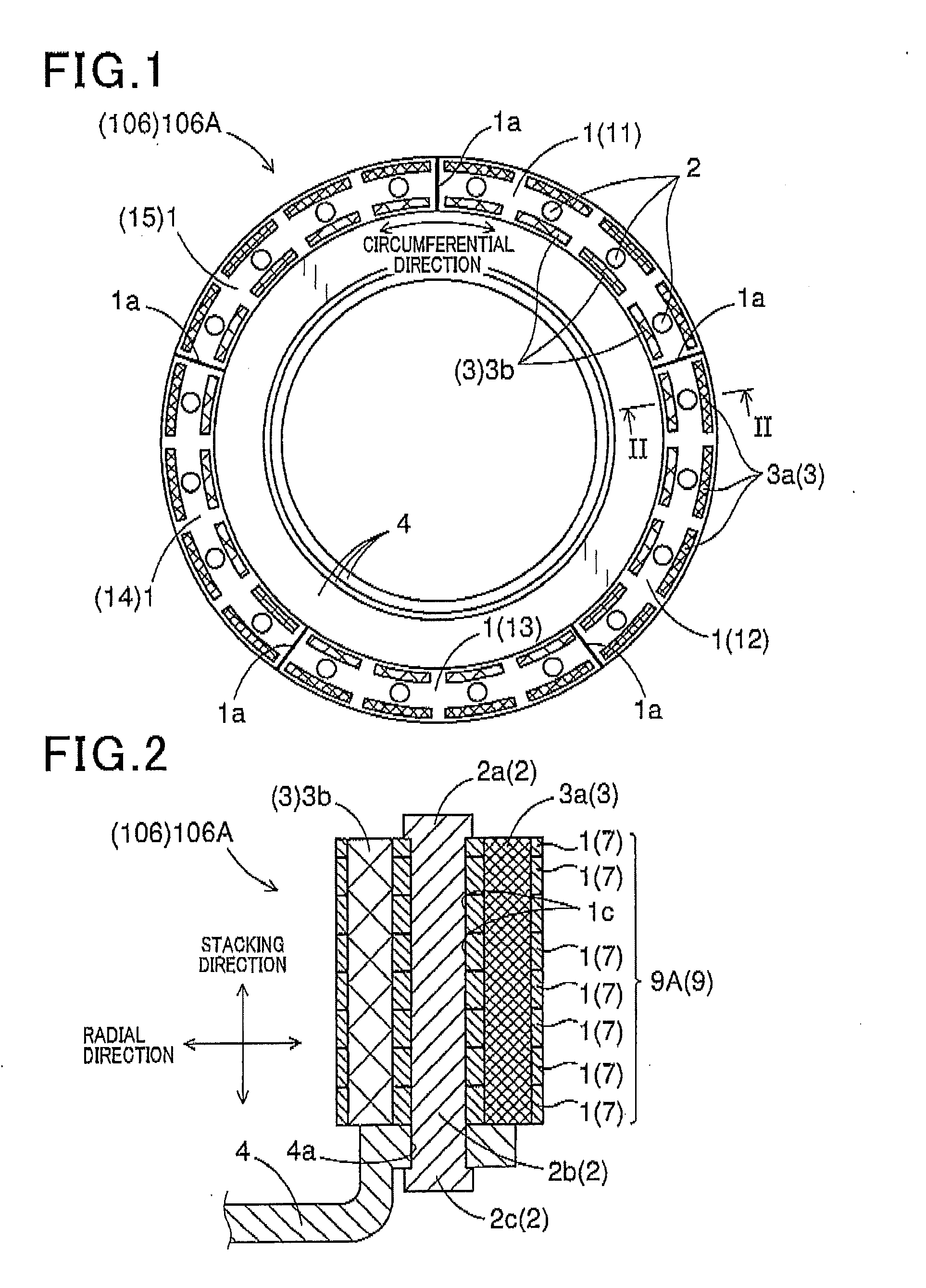
[0044]FIGS. 1-2 show the overall configuration of a rotor 106A which is an example of a rotor 106 according to the present invention. The rotor 106A includes a rotor core 9A, a plurality of rivets 2, a plurality of radially outer permanent magnets 3a, a plurality of radially inner permanent magnets 3b and a disc 4. The rotor core 9A is an example of a rotor core 9 according to the present invention. In addition, the rivets 2 correspond to “fixing members” of the present invention; the disc 4 corresponds to “a fixed member” of the present invention.

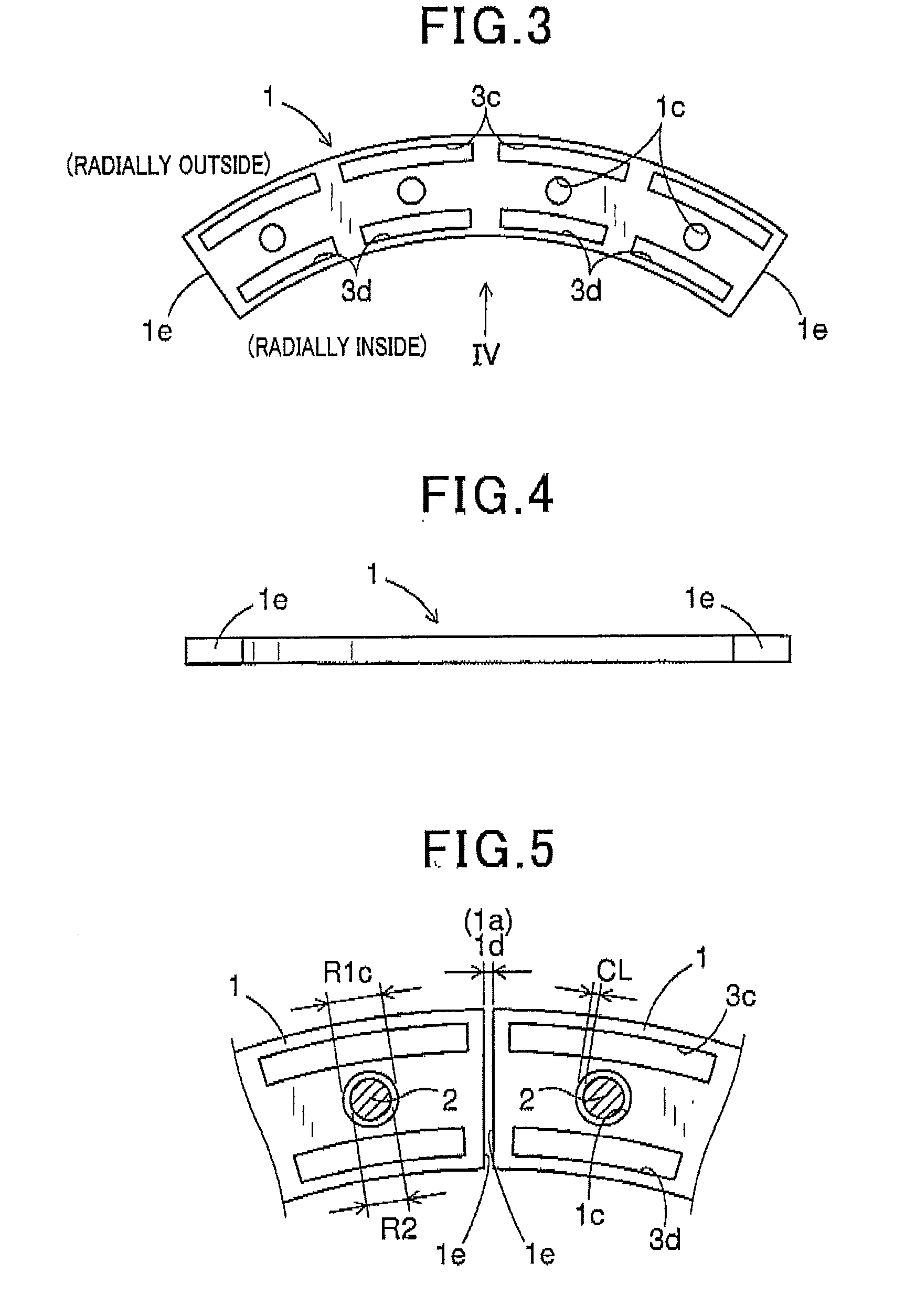
[0045]The rotor core 9A includes a plurality of annular bodies 7 that are stacked in layers in an axial direction of the rotor core 9A, Each of the annular bodies 7 is comprised of a plurality of core segments 1 that are arranged along a circumferential direction of the rotor core 9A (see also FIGS, 6-9). Accordingly, in each of the annular bodies...

second embodiment

[0076]A second exemplary embodiment will be described hereinafter with reference to FIGS. 15-19.

[0077]FIG. 18 shows the overall configuration of a rotor 106B which is another example of the rotor 106 according to the present invention. The rotor 106E includes a rotor core 9B, a plurality of rivets 2, a plurality of radially outer permanent magnets 3a, a plurality of radially inner permanent magnets 3b and a disc 4. The rotor core 9B is another example of the rotor core 9 according to the present invention. The rotor 106B differs from the rotor 106A of the first embodiment only in that the rotor core 9B of the rotor 106B further includes a first plate 5 in comparison with the rotor core 9A of the rotor 106A. The first plate 5 is made of a nonmagnetic material and has a smaller thickness than the core segments 1.

[0078]FIG. 15 shows an annular plate 5A which is an example of the first plate 5. The annular plate 5A has a plate body 5a and a plurality of through-holes 5c formed in the pl...

third embodiment

[0087]A third exemplary embodiment will be described hereinafter with reference to FIGS. 20-24.

[0088]FIGS. 20 and 24 show the overall configuration of a rotor 106C which is yet another example of the rotor 106 according to the present invention. The rotor 106C includes a rotor core 9C, a plurality of rivets 2, a plurality of radially outer permanent magnets 3a, a plurality of radially inner permanent magnets 3b and a disc 4. The rotor core 9C is yet another example of the rotor core 9 according to the present invention. The rotor 1060 differs from the rotor 106E of the second embodiment only in that the rotor core 9C of the rotor 1060 further includes a second plate 6 in comparison with the rotor core 9B of the rotor 106B.

[0089]The second plate 6 is formed of a magnetic material into a predetermined shape. The second plate 6 has a smaller thickness than the core segments 1.

[0090]FIG. 21 shows an annular plate 6A which is an example of the second plate 6. The annular plate 6A has a p...


PUM


Abstract

A rotor includes a rotor core and permanent magnets. The rotor core includes annular bodies that are stacked in a stacking direction and each formed of core segments arranged along a circumferential direction. The number of the core segments in each of the annular bodies is set based on k, where k is the number of magnetic poles formed by the permanent magnets. The rotor core has n through-holes, where n≧k. The rotor further includes n fixing members each of which extends in the stacking direction through one corresponding through-hole of the rotor core. Between each circumferentially adjacent pair of the core segments, there is formed a gap that is greater than a clearance provided between the through-holes of the rotor core and the fixing members. At least one of the annular bodies is circumferentially offset from another annular body by an integer multiple of one magnetic pole.

Description

CROSS-REFERENCE TO RELATED APPLICATION[0001]This application is based on and claims priority from Japanese Patent Application No. 2014-200242 filed on Sep. 30, 2014, the content of which is hereby incorporated by reference in its entirety into this application.BACKGROUND[0002]1. Technical Field[0003]The present invention relates to a rotor which includes a rotor core formed into a predetermined shape by arranging in a circumferential direction and stacking in a stacking direction a plurality of core segments, and to a rotating electric machine which includes the rotor.[0004]2. Description of Related Art[0005]Conventionally, in consideration of centrifugal force, rotors for rotating electric machines generally employ cores that are formed into one piece by, for example, blanking.[0006]On the other hand, there is disclosed, for example in Japanese Patent Application Publication No JP2002262496A, a rotor core that is formed of core segments and designed to withstand centrifugal force. ...

Claims


Application Information

Patent Timeline
Patent Type & Authority Applications(United States)
IPC IPC(8): H02K1/27
CPCH02K1/2773H02K1/27H02K1/28H02K2201/06
Inventor MAEKAWA, TAKEOKONDOU, KEIJIKUSASE, SHIN
Owner DENSO CORP
Why Eureka
Try Eureka