Wound transformer core and method of manufacture

a transformer core and core technology, applied in the field of wound transformer cores, can solve the problems of high maintenance cost, high cost of cutting and stacking sheets, and high cost of flat stack technology, and achieve the effect of saving time and cost, and reducing the cost of flat stacking

Active Publication Date: 2016-01-21
EARHART KEITH D
View PDF17 Cites 2 Cited by
  • Summary
  • Abstract
  • Description
  • Claims
  • Application Information

AI Technical Summary

Benefits of technology

[0037]The tapers along the left and right sides of the one or more strips strip may also be formed in a non-linear fashion to define curved left and right sides. It will be appreciated that the curvature of the left and right sides of the strip can be chosen so that when the one or more strips are wound the resultant core cross-section through a leg of the core will be circular thereby minimizing the air gap between the core leg and a surrounding tube-wound coil.

Problems solved by technology

Firstly, the machinery for cutting and stacking the sheets is extremely expensive and due to the repetitive cutting actions and back and forth movements, is prone to frequent failure and requires a high degree of maintenance.
Secondly, the flat stack technology becomes very time consuming and costly when using thinner material.
The flat stack technology discussed above therefore does not provide a satisfactory solution to making transformer cores using these materials.
Thus, although these materials display lower losses, the flat stack manufacturing process does not lend itself to making cores from the material.
Also, the winding of the amorphous core into a generally rectangular shape can detrimentally impact the performance since stresses are introduced when forming the corners of the core.
Additional problems are encountered specifically when dealing with amorphous metal as the magnetic core material.
Amorphous metal also lacks the structural integrity of silicon steel, displaying instead the floppiness of wet tissue paper even though it has quite high tensile strength.
Thin materials such as amorphous metal and nano-grain steel also require 5 to 10 times more layers to build up the core, requiring a longer winding process and more difficulties with unlacing and re-lacing of the core in order to land the coils on the core.
Amorphous metal also becomes quite brittle once annealed, making this core manufacturing process quite complex when compared to the core manufactured from silicon steel.
The brittleness of annealed amorphous metal leads to inevitable breakage and flaking when unlacing and re-lacing an amorphous core.

Method used


Image

  • Wound transformer core and method of manufacture
  • Wound transformer core and method of manufacture
  • Wound transformer core and method of manufacture

Examples


Embodiment Construction

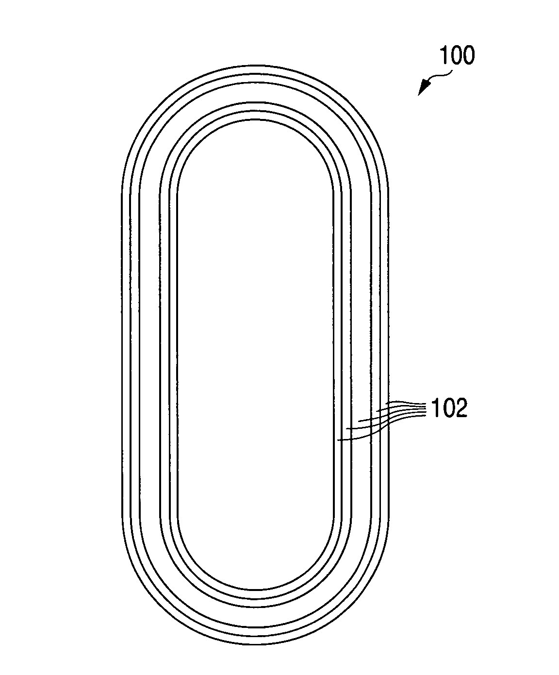
[0063]The present invention provides a wound transformer core that is produced as a new ring-like wound core configuration that allows coils subsequently to be wound on the legs of the core without cutting the wound layers of the core.

[0064]FIG. 1 shows a top view of one embodiment of a wound transformer core 100 of the invention. The ring-like structure of the core 100 is made up of multiple rings 102 of magnetic steel, e.g., amorphous metal strip or nano-grain steel material or silicon steel, of different widths (not shown in FIG. 1) wound on top of one another. Insofar as the thickness of the magnetic steel is less than 2.5 mil, e.g., amorphous metal or nano-grain steel, the strip material will be referred to herein in as thin-strip metal.

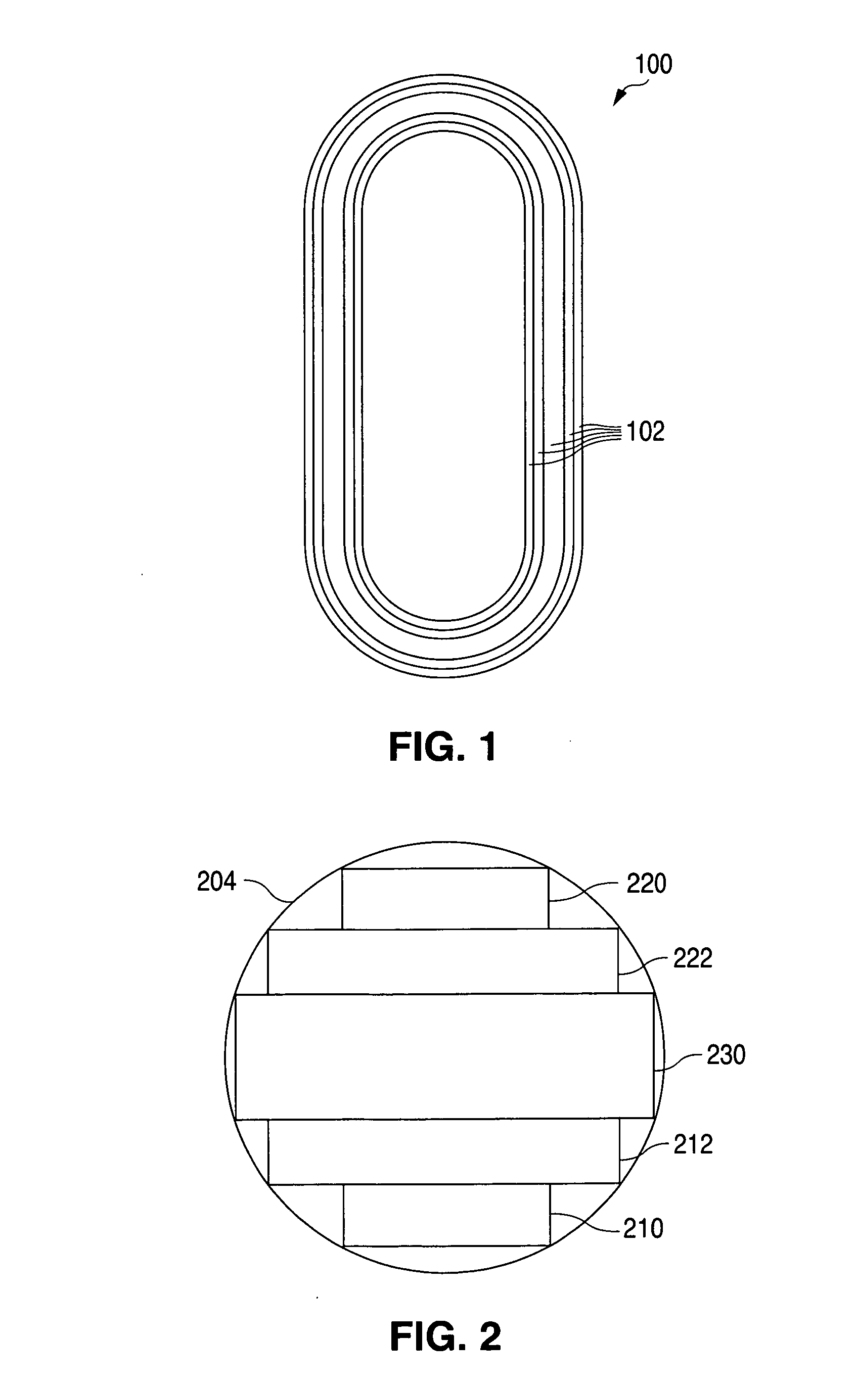
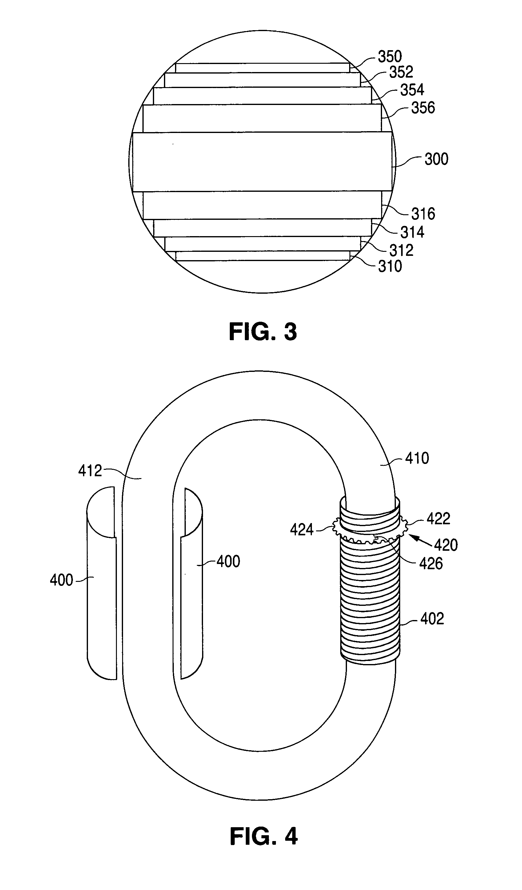
[0065]The different widths of the rings 102 are best illustrated in the cross-sectional views of FIGS. 2 and 3. The ring-like structure defining the core 200 is made up of multiple rings, each of which is wound from one or more strips of magneti...


PUM

PropertyMeasurementUnit
thickaaaaaaaaaa
thickaaaaaaaaaa
thickaaaaaaaaaa

Abstract

In a single phase transformer core and transformer, thin-strip metal is wound into multiple rings of different widths and arranged to define a ring-like structure having a stepped, substantially circular cross-section without any cuts or gaps in the magnetic path, or the core is wound from a tapered strip that is configured to define a substantially circular cross-section when wound, while in a three phase transformer core and transformer two inner frames, each made of one or more wound rings are arranged side-by-side and an outer frame of one or more rings is wound around the two inner frames, the core being covered with epoxy prior to winding coils on it.

Description

[0001]The present application claims priority from U.S. Provisional Patent Application 61 / 627,916 filed Oct. 19, 2011 in the name of Keith D. Earhart and John S. Hurst, U.S. Provisional Patent Application 61 / 634,123 filed Feb. 22, 2012 in the name of Keith D. Earhart, and U.S. patent application Ser. No. 13 / 573,986 filed Oct. 18, 2012.FIELD OF THE INVENTION[0002]The present invention relates to wound transformer cores.BACKGROUND OF THE INVENTION[0003]Transformers cores are typically made of layers of magnetic steel in order to reduce eddy current effects. One approach has been to manufacture stacked cores in which Silicon Steel is cut into lengths and stacked on top of one another to form a stack of laminated steel. Typically stacks are arranged in core configurations e.g., a FIG. 8 configuration in which the stacks are intertwined at their corners. This approach works adequately when dealing with Silicon Steel sheets that are typically of the order of 10 mil thick. However the down...

Claims


Application Information

Patent Timeline
Patent Type & Authority Applications(United States)
IPC IPC(8): H01F41/02
CPCH01F41/0206H01F41/0226H01F27/25H01F41/06Y10T29/49071
Inventor EARHART, KEITH D.HURST, JOHN S.
Owner EARHART KEITH D
Why Eureka
Try Eureka