Cam jet dispensing device

A dispensing device and jet-type technology, which is applied in the field of jet-dispensing devices, can solve the problems of affecting the attraction force of the electromagnet, the wear of the displacement amplification mechanism, and the large output force of the piezoelectric stack, so as to achieve fast up and down movement of the firing pin, The effect of stable rotation speed and low coupling coefficient

Inactive Publication Date: 2013-07-31
JILIN UNIV
View PDF5 Cites 19 Cited by
  • Summary
  • Abstract
  • Description
  • Claims
  • Application Information

AI Technical Summary

Problems solved by technology

Therefore, it is difficult to accurately control the movement speed and stroke of the striker
[0005] (2) In the piezoelectric ceramic jet dispensing device, the displacement generated by the piezoelectric stack is small and cannot be directly applied to the jet dispensing device. It needs to be amplified before it can be applied. The displacement amplification structure is complex, which increases the dispensing device complexity
At the same time, the output force of the piezoelectric stack is large, resulting in serious wear and tear of the displacement amplification mechanism, and the displacement amplification ratio of the displacement amplification mechanism will decrease as the working time increases
[0006] (3) The electromagnet in the electromagnetic jet dispensing device is prone to eddy current effect, which affects the attraction force of the electromagnet, and finally it is difficult to realize the precise control of the speed and stroke of the firing pin

Method used


Image

  • Cam jet dispensing device
  • Cam jet dispensing device
  • Cam jet dispensing device

Examples


Embodiment Construction

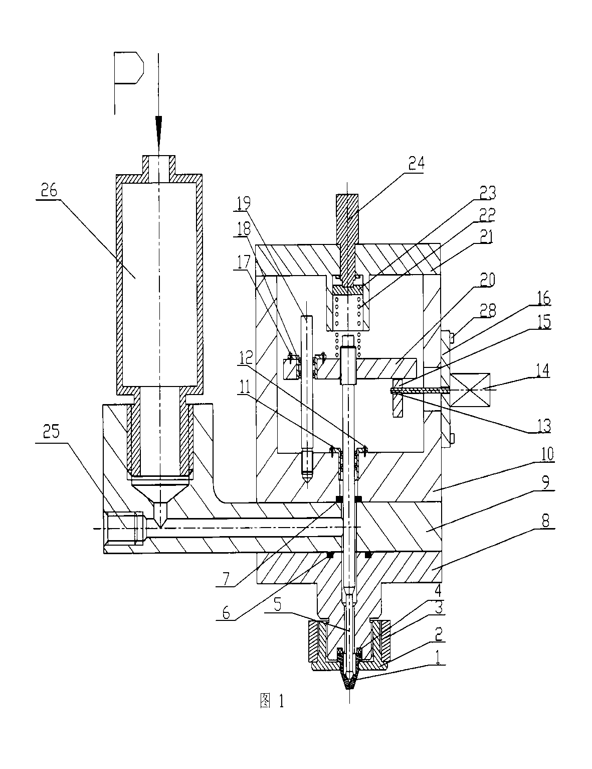
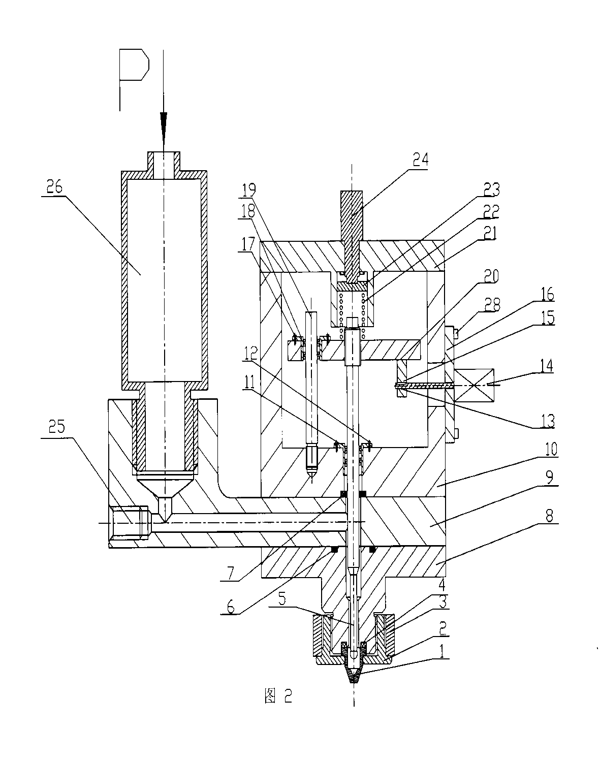
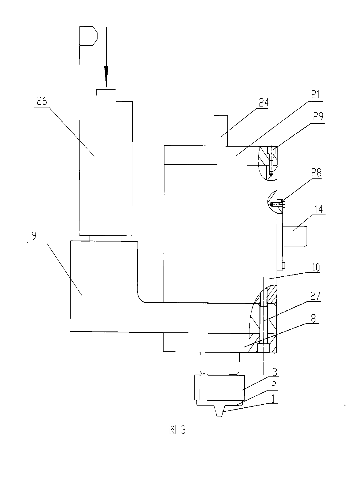
[0017] refer to figure 1 , figure 2 , image 3 , The cam jet dispensing device consists of nozzle 1, fixed nut 2, heater 3, O-ring 4, striker 5, O-ring 6, PTFE sealing ring 7, nozzle interface seat 8, glue inlet seat 9, machine Frame 10, linear bearing 11, screw 12, key 13, servo motor 14, cam 15, servo motor seat 16, screw 17, linear bearing 18, anti-rotation lever 19, moving arm 20, frame cover 21, spring 22, pressure Sheet 23, differential head 24, screw 25, rubber tube 26, screw 27, screw 28, screw 29 are formed.

[0018] The fixing nut 2 fixes the nozzle 1 on the bottom of the nozzle interface seat 8 . An O-ring 4 is installed on the top of the nozzle 1, and its function is to prevent glue with a certain pressure from leaking from the gap between the nozzle 1 and the nozzle interface seat 8. A heater 3 is installed on the fixed nut 2 to heat the glue at the nozzle 1 to reduce its viscosity, which is beneficial for the glue to be sprayed smoothly from the nozzle 1 to...


PUM


Abstract

The invention discloses a cam jet dispensing device mainly composed of a servo nozzle 1, a firing pin 5, a servo motor 14, a cam 15, a movement arm 20, a micrometer head 24, a pressing plate 23, and a spring 22. The firing pin 5 is arranged on the movement arm 20, such that a movement part is formed. The firing pin 5, the movement arm 20, and the cam 15 form a cam mechanism. The servo motor 14 drives the cam mechanism to rotate. The cam mechanism drives the firing pin 5 to move up and down, such that the closing and opening of the firing pin 5 and the nozzle 1 are realized. High-pressure glue at the nozzle 1 is jet through the nozzle 1. The device has the main characteristics that: (1) power of the device used for driving the firing pin is provided by the cam rotated by the servo motor; the rotation speed of the servo motor is stable; firing pin moves fast up and down; and jet frequency is high; and (2) firing pin movement speed of the device is determined by motor rotation speed; the amount of coupling coefficients is low, and controlling is convenient.

Description

technical field [0001] The invention relates to a jetting glue dispensing device, in particular to a jetting glue dispensing device powered by a cam driven by a servo motor. Background technique [0002] Dispensing units are used in electronics manufacturing to dispense viscous liquids onto workpieces. The jet dispensing device can quickly distribute viscous liquid to the surface of the workpiece. [0003] Jet dispensing devices are mainly divided into pneumatic jet dispensing devices, piezoelectric ceramic jet dispensing devices, and electromagnetic jet dispensing devices according to the driving mode. At present, there are some shortcomings in these kinds of glue dispensing and dispensing devices, the main performances are as follows: [0004] (1) Pneumatic injection dispensing device mainly drives the striker through the double-stroke piston, but the movement speed and stroke of the striker are affected by factors such as intake pressure, exhaust volume, piston stroke, ...

Claims


Application Information

Patent Timeline
Patent Type & Authority Applications(China)
IPC IPC(8): B05C5/02B05C11/10
Inventor 路崧刘建芳焦晓阳柳沁张凯李彪刘洋顾守东陈洪霞杨继光
Owner JILIN UNIV
Why Eureka
Try Eureka