Oil separator

A grease separation and grease technology, applied in chemical instruments and methods, water/sewage multi-stage treatment, water/sludge/sewage treatment, etc., can solve problems such as unsatisfactory water quality, low treatment efficiency, and large floor area. To achieve the effect of easy maintenance and cleaning, cleanliness and sanitation, and reasonable structure

Active Publication Date: 2013-07-31
BEIJING HUANZHI ENVIRONMENTAL PROTECTION EQUIP
View PDF5 Cites 5 Cited by
  • Summary
  • Abstract
  • Description
  • Claims
  • Application Information

AI Technical Summary

Problems solved by technology

[0003] In the past, most of the traditional grease traps were used to treat catering sewage, but this kind of treatment has low efficiency and poor effect, and occupies a large area
Recently, oil separators have been installed in the kitchens of buildings to remove slag and oil. The advantages of oil separators over grease traps are that they are more efficient in oil-water separation, better in oil removal, and occupy less space. The area is small, but there are also many disadvantages. For example, oil removal and slag removal usually require a lot of manual work, which is inconvenient to operate and easily pollutes the environment. Moreover, the water quality after oil-water separation and slag removal cannot meet the increasing national living standards. Sewage Discharge Standard Requirements

Method used


Image

  • Oil separator
  • Oil separator
  • Oil separator

Examples


Embodiment Construction

[0064] The embodiments of the present invention will be further described below in conjunction with the drawings and embodiments.

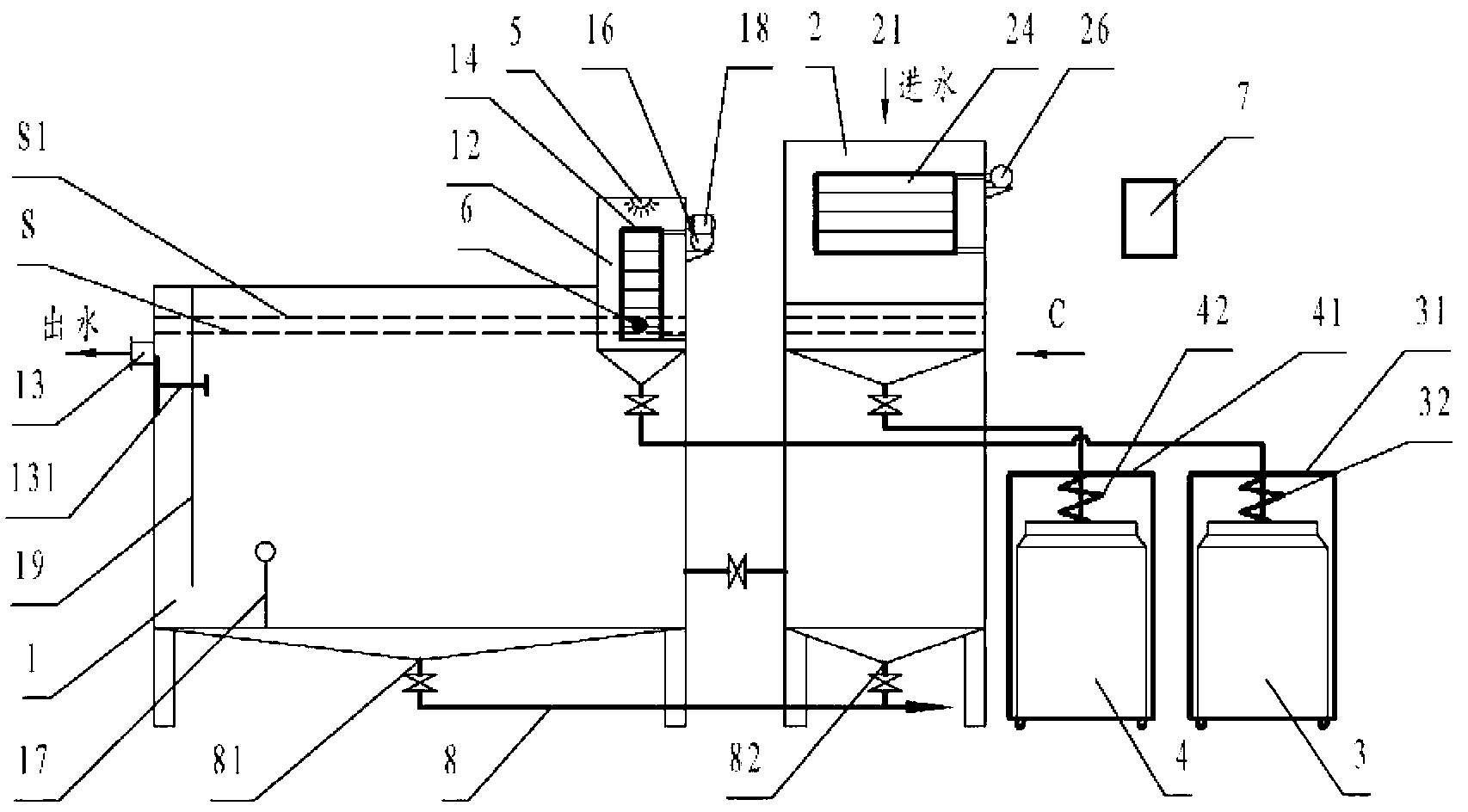
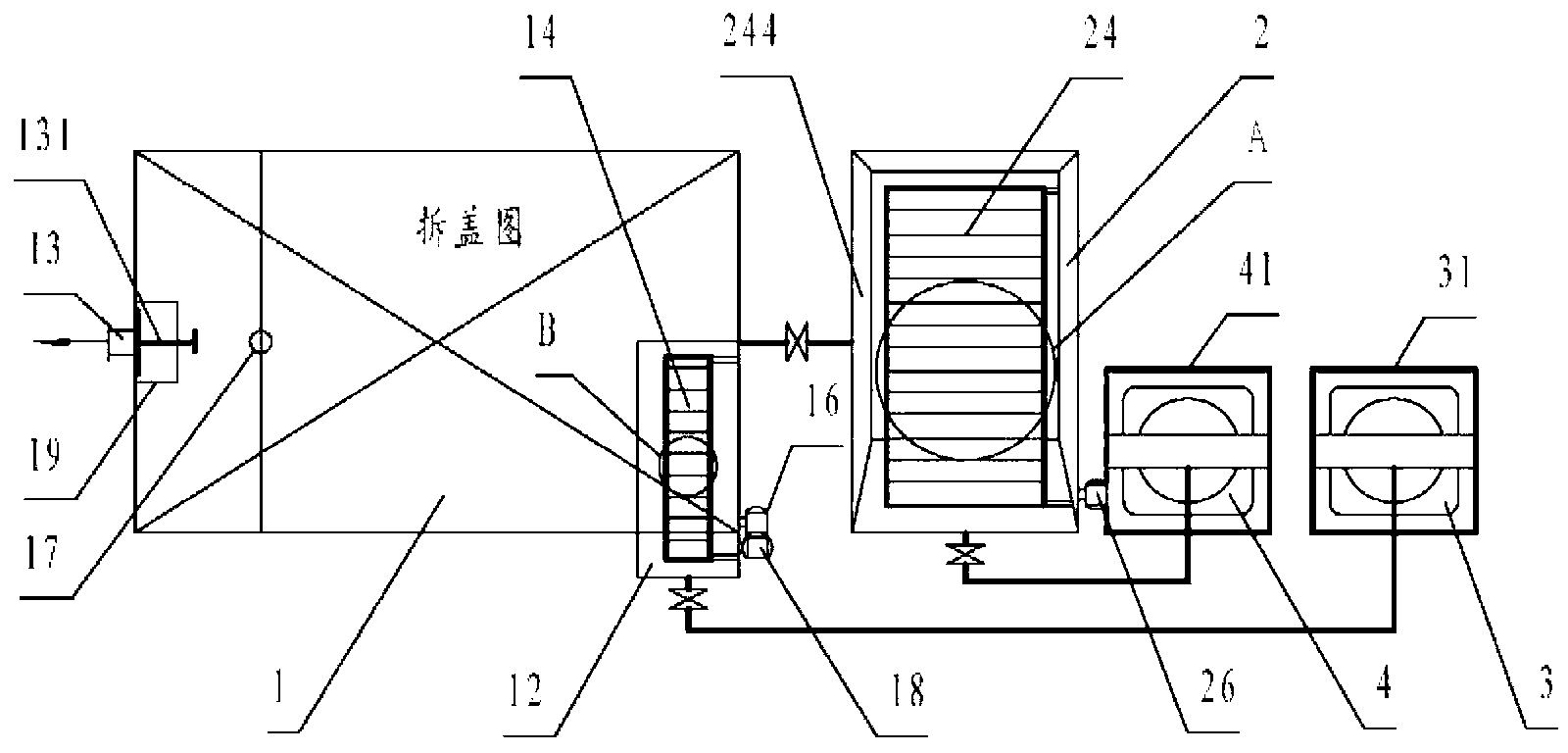
[0065] figure 1 is the main sectional view of the grease separator. figure 2 yes figure 1 Top view of the grease separator shown.

[0066] see figure 1 with figure 2 According to one embodiment of the present invention, the grease separator of the present invention includes a degreasing tank 1 and a deslagging tank 2 which is separately provided from the degreasing tank 1 .

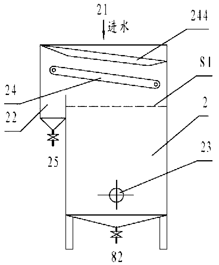
[0067] The slag removal box 2 includes: a water inlet 21, which is arranged on the top of the slag removal box 2, or a water inlet pipe with a corresponding size, shape and orientation can be provided according to the different needs of users, and kitchen sewage is introduced into the slag removal box 2 through the water inlet 21. The liquid level S1 is formed in the slag removal box 2 and in the oil removal box 1 and the slag removal box 2; the slag discharge area 22 ...


PUM


Abstract

The invention discloses an oil separator which comprises an oil removal box and a slag removal box separated from the oil removal box, wherein the slag removal box comprises a slag discharge area which is arranged on one side of the slag removal box; the kitchen sewage is led into the slag removal box; the slag contained in the sewage is filtered by a chain plate type conveying belt in the slag removal box and conveyed to the slag discharge area as well as discharged to the outside from the slag discharge area; the sewage after slag removal flows into the oil removal box for oil removal; and the oil contained in the sewage is discharged to the outside. The oil separator disclosed by the invention realizes automatic oil discharge and automatic slag discharge functions, and is reasonable in structure and simple and convenient to operate.

Description

technical field [0001] The invention relates to a wastewater treatment device for catering industry, in particular to a grease separator. Background technique [0002] There are usually kitchens in various buildings such as hotels, guesthouses, school canteens, restaurants, restaurants, office buildings and residential buildings. The catering sewage discharged from the kitchen contains a large amount of dregs and grease, and cannot be directly connected to the sewer system in cities and towns. , it is necessary to carry out deslagging and degreasing treatment first. [0003] In the past, traditional grease traps were mostly used to treat catering sewage, but this kind of treatment has low efficiency, poor effect and occupies a large area. Recently, oil separators have been installed in the kitchens of buildings to remove slag and oil. The advantages of oil separators over grease traps are that they are more efficient in oil-water separation, better in oil removal, and occup...

Claims


Application Information

Patent Timeline
Patent Type & Authority Applications(China)
IPC IPC(8): C02F9/02C02F9/08
Inventor 刘雯
Owner BEIJING HUANZHI ENVIRONMENTAL PROTECTION EQUIP
Why Eureka
Try Eureka