Rack particularly for equipment cabinet

A frame and instrument cabinet technology, which is applied to the frame of the substation/switchgear, the layout details of the substation/switch, electrical components, etc., can solve the problem of the frame's laborious transportation, and achieve the effect of simple connection

Active Publication Date: 2013-07-31
RITTALWERK RUDOLF LOH GMBH & CO KG
View PDF10 Cites 13 Cited by
  • Summary
  • Abstract
  • Description
  • Claims
  • Application Information

AI Technical Summary

Problems solved by technology

But there are also cases when pre-assembled frames can only be transported with difficulty, for example when getting in and out of narrow stairwells or elevators is difficult

Method used


Image

  • Rack particularly for equipment cabinet
  • Rack particularly for equipment cabinet
  • Rack particularly for equipment cabinet

Examples


Embodiment Construction

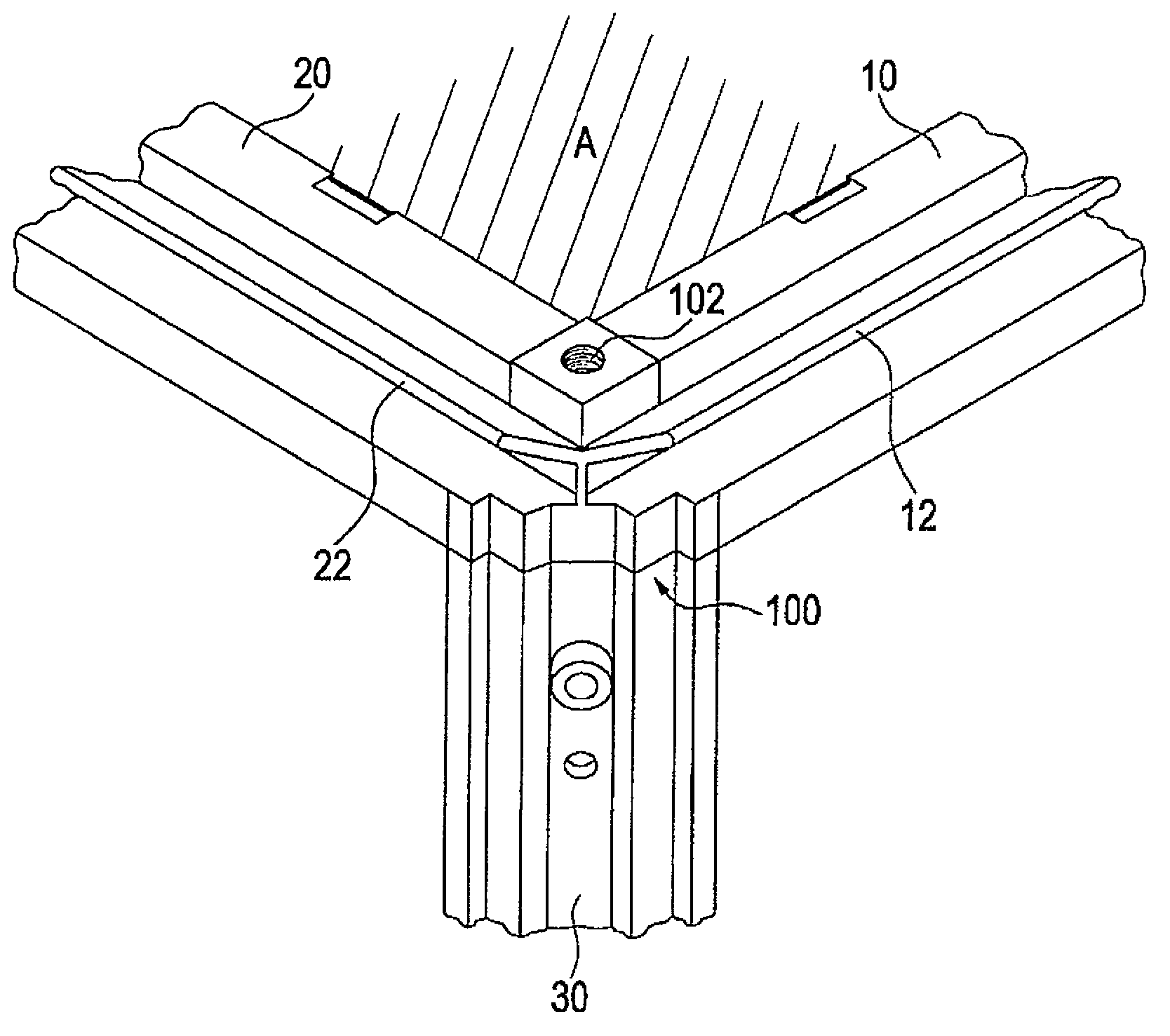
[0023] figure 1 Schematic representation of a corner of a frame according to the invention, which is particularly conceivable for use in switchgear cabinets.

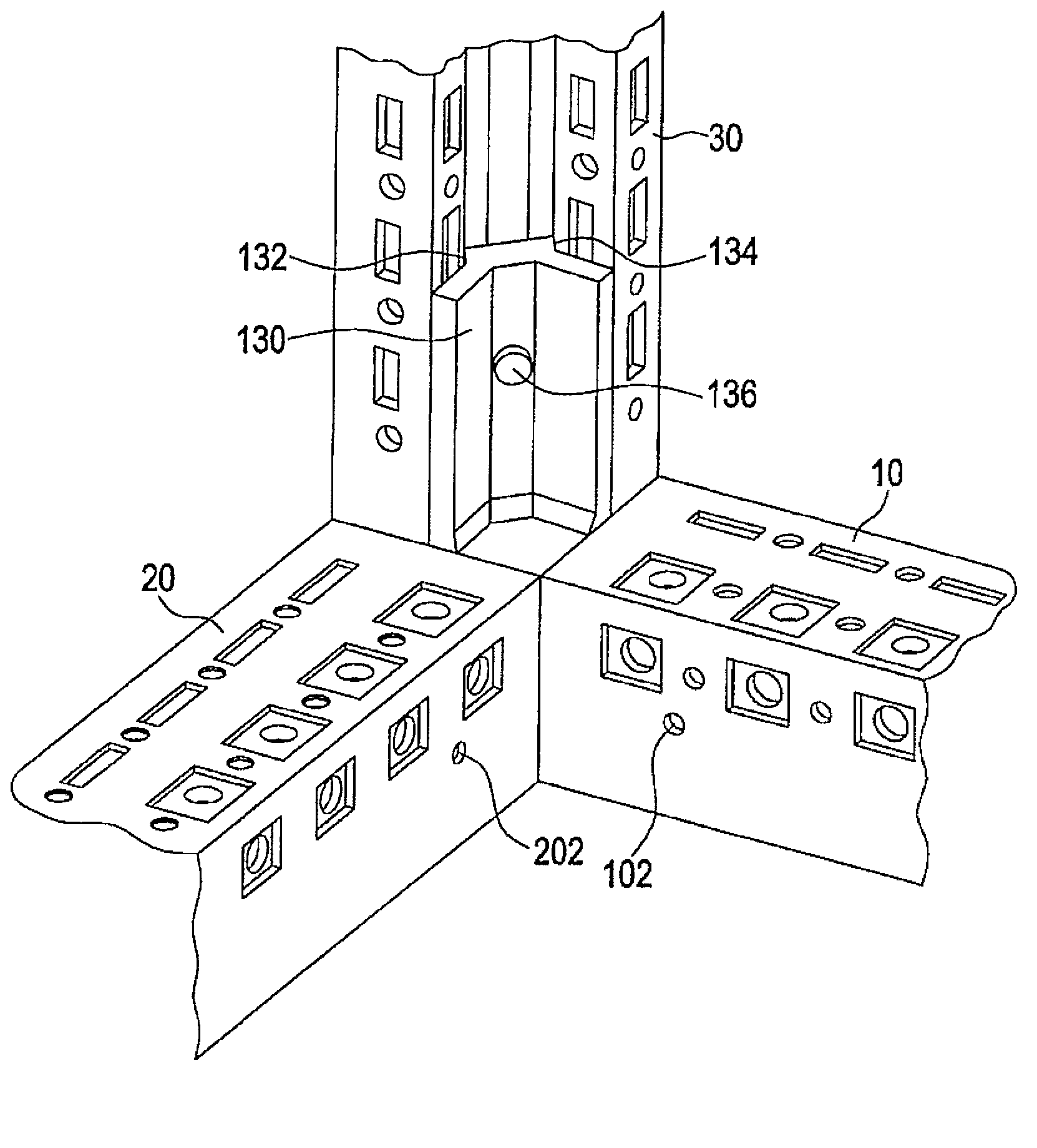
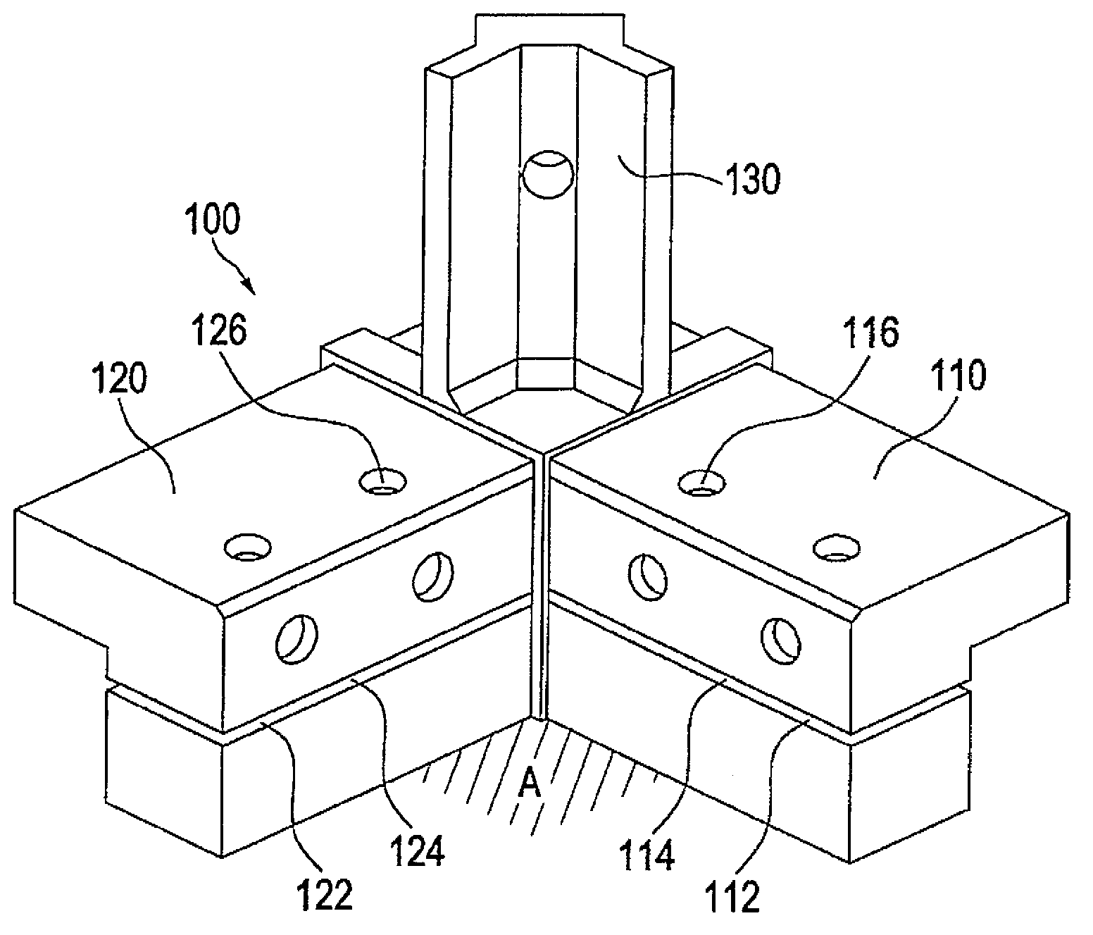
[0024] The frame according to the invention consists of profiles 10, 20, 30 which are passed through image 3 The corner connector 100 shown in detail in the connection. Here, two profiles adjacent to each other define a reference plane, which in the description of the invention is only used to clarify the spatial relationship of the components and has nothing to do with the physical mounting plane of the frame. In particular, the profile 10 extending in the transverse direction and the profile 20 extending in the depth direction define the reference plane A. As shown in FIG.

[0025] Each profile 10, 20, 30 is plugged into and fixed on the corresponding plug-in piece of the corner connector 100 which will be described later. The corner connector 100 has threaded holes 102 in its exposed corner regions not covered by...


PUM


Abstract

The invention relates to a rack, particularly for equipment cabinets, which comprise section bars (10, 20, 30 ) extending in the transverse direction, in the depth direction and / or in the vertical direction, wherein, two adjacent section bars (10, 20) determine a reference plane (A), and the section bar is connected by a corner connector (100) with plug connectors, and each section bar is covered and fixed on the plug connecters, and at least one plug (110, 120) has an open slot (112, 122) continuously extended and parallel to the relative reference plane, and section bar relative to the plug has pores (102, 202) in the area of the plug connector at the height of the groove, and a fixing plug crosses the pore and is parallel to the reference plane, and pores sink into the groove with force and/or in shape matching type; the corner connector (100) has a plug connector (130), and the plug connector comprises side concaves (132, 134) which are mutually opposite for jointing dovetail joint outline of the vertically extending profile (30) with force and/or in shape matching type.

Description

technical field [0001] The invention relates to a frame, in particular for a switchgear cabinet, comprising a profile extending in the transverse direction, in the depth direction and / or in the vertical direction, wherein the profile extending in the vertical direction is designed as a mirror image with respect to the diagonal of the cross section , as well as two profile wings that can be oriented perpendicularly to the outside of the frame, are made with fixed mountings and are connected to each other by a connecting section that forms an inclined outer edge, wherein the profile wings face the connecting section on the outside transition to a double-layer sealing web or a U-shaped support web, comprising a support web extending parallel to the relevant outer side, wherein a web section facing the connection section stands perpendicularly to the outer side and can also have a length of zero, and wherein, The profile flank also transitions at the edge opposite the connecting s...

Claims


Application Information

Patent Timeline
Patent Type & Authority Applications(China)
IPC IPC(8): H02B1/01
CPCH02B1/014H02B1/01
Inventor H.瓦吉纳C.舍夫勒
Owner RITTALWERK RUDOLF LOH GMBH & CO KG
Why Eureka
Try Eureka