Three-phase soft-switched PCF rectifiers

一种三相、升压整流的技术,应用在交流功率输入变换为直流功率输出、高效电力电子转换、输出功率的转换装置等方向,能够解决影响电路尺寸、增加成本等问题

Inactive Publication Date: 2013-07-31
DELTA ELECTRONICS INC
View PDF2 Cites 38 Cited by
  • Summary
  • Abstract
  • Description
  • Claims
  • Application Information

AI Technical Summary

Problems solved by technology

In order to use the split capacitor approach, these circuits require supplemental voltage balancing circuitry, which further increases cost and may also affect circuit size

Method used


Image

  • Three-phase soft-switched PCF rectifiers
  • Three-phase soft-switched PCF rectifiers
  • Three-phase soft-switched PCF rectifiers

Examples


Embodiment Construction

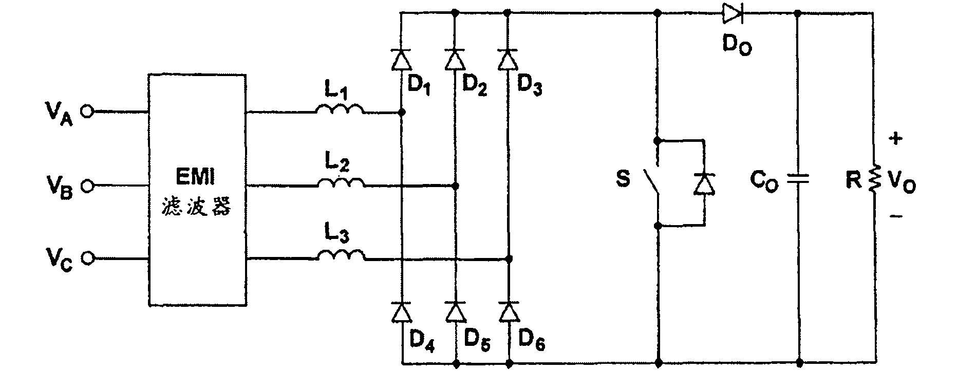
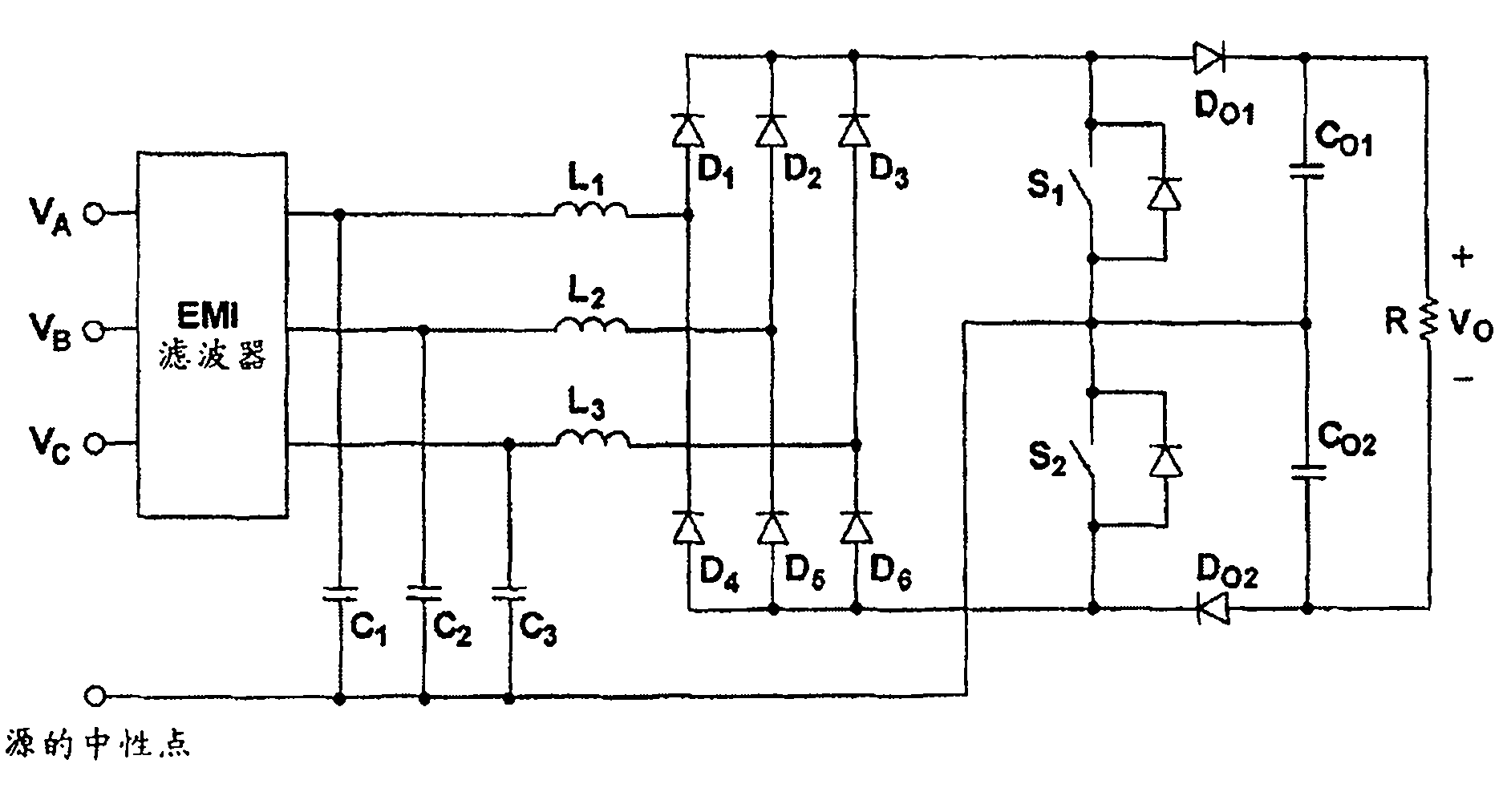
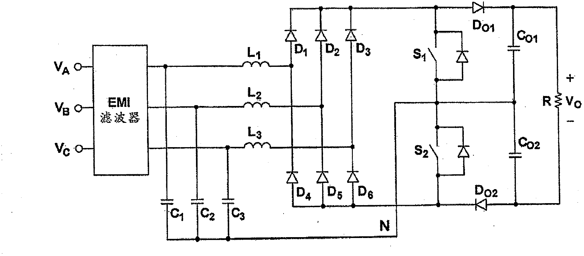
[0073] The present invention relates to a three-phase rectifier implementation that provides low THD and high PF of input current and soft switching of switches over a wide load range. A non-isolated implementation and an isolated implementation are described below. The non-isolated implementation reduces common-mode noise and provides automatic balancing of the split capacitors when using series-connected downconverters. An isolated implementation provides galvanic isolation of the output from the input side. Furthermore, isolated implementations can tightly control their output voltages to minimize unwanted voltage ripple by employing additional phase shifting or pulse width modulation (PWM) control with the added switches. Circuits can also be interleaved to reduce their current and voltage ripple.

[0074] Figure 6 A block diagram showing a three-phase two-switch ZVS PFC DCM low input current harmonic boost rectifier according to an embodiment of the present invention....


PUM


Abstract

A low input-current harmonic three-phase boost rectifier includes an input stage for receiving a three-phase input voltage in relation to a neutral node and an output stage adapted to couple to at least one load. The rectifier further includes one or more switching converter stages, each having a plurality of switches coupled to the neutral node, the plurality of switches operating with a fixed duty cycle, the fixed duty cycle being a substantially 50% duty cycle. The rectifier further includes one or more controllers adapted to vary the switching frequency of the plurality of switches based on at least one of a condition of the at least one load or the input voltage and includes one or more decoupling stages, each including one or more inductive elements adapted to inductively decouple the output stage from at least one of the one or more switching converter stages.

Description

technical field [0001] The present invention generally relates to front-end rectifiers with Power Factor Correction (PFC), and more particularly to three-phase PFC rectifiers. Background technique [0002] It is now well established that a three-phase power factor correction (PFC) rectifier with three or more switches shows Better power factor (PF) and total harmonic distortion (Total Harmonic Distortion, THD). However, due to their simplicity and low cost, single and two-switch rectifiers are still very attractive for deployment in cost-sensitive applications. [0003] figure 1 The most commonly used prior art three-phase single-switch rectifier is shown. This simple three-phase boost (boost) rectifier performs a low-harmonic wave rectification. It is well known that in DCM operation, the line current of the boost rectifier naturally tends to follow the respective line voltage, with the result that the THD and PF of the line current are improved. Since the inductor cu...

Claims


Application Information

Patent Timeline
Patent Type & Authority Applications(China)
IPC IPC(8): H02M7/217H02M1/12H02M1/44H02M1/42
CPCH02M1/12Y02B70/126H02M7/217H02M1/44H02M1/4216H02M1/42Y02B70/10Y02P80/10
Inventor 扬泰克·简米兰·乔瓦诺维克
Owner DELTA ELECTRONICS INC
Why Eureka
Try Eureka