Method and apparatus for protecting an optical detection device from contamination

An optical detector and detector technology, applied in the field of optical detectors, can solve problems such as being unsuitable for cameras

Inactive Publication Date: 2013-07-31
DELAVAL HLDG AB
View PDF3 Cites 4 Cited by
  • Summary
  • Abstract
  • Description
  • Claims
  • Application Information

AI Technical Summary

Problems solved by technology

Therefore, this arrangement is not inherently suitable for use near the floor of a warehouse or milking parlour, for example at roughly teat level

Method used


Image

  • Method and apparatus for protecting an optical detection device from contamination
  • Method and apparatus for protecting an optical detection device from contamination
  • Method and apparatus for protecting an optical detection device from contamination

Examples


Embodiment Construction

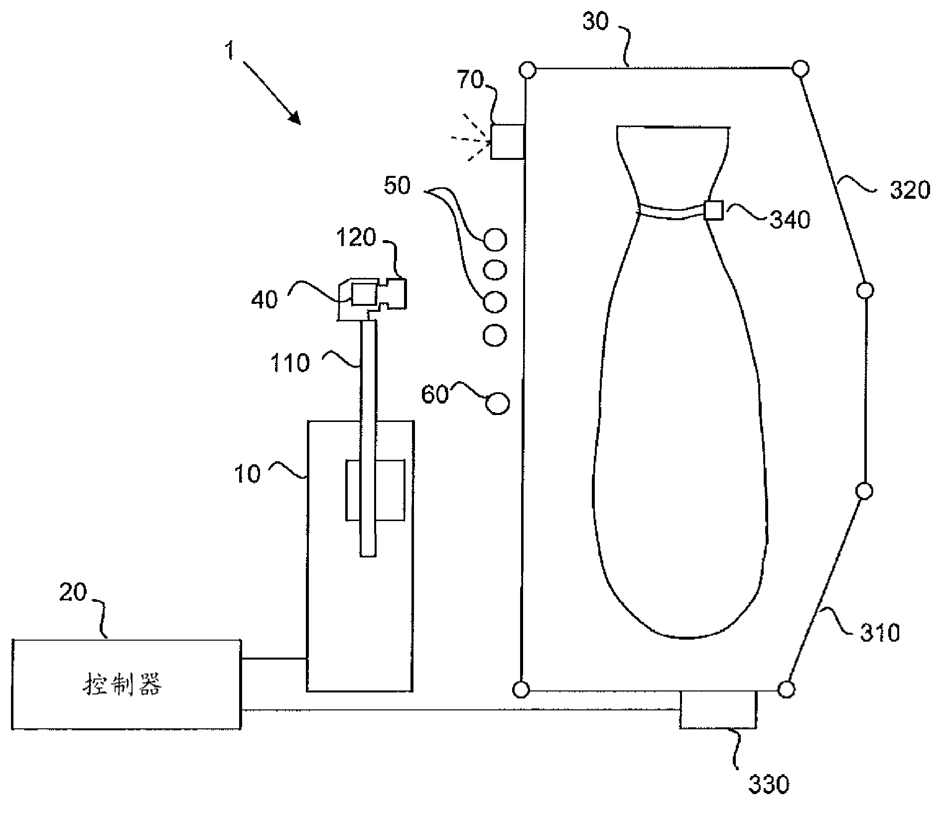
[0026] figure 1 An automatic milking system is shown, which includes a milking shed 30 for enclosing animals to be milked and a milking machine 1 arranged on one side of the milking shed 30 . The milk house 30 includes an entrance door 310 and an exit door 320 . An identification device 330 is installed on or next to the milk barn 30 near the entrance door 310 . This device 330 detects the unique identification of the animal standing in front of the barn by detecting or interrogating a transponder 340 carried by the animal (eg on a collar) and holding a unique identification number or code assigned to the animal. Control of these doors will be described in more detail below. The milking machine 1 comprises a machine arm arrangement 10 as well as a number of other components which are not shown in the figures but are conventionally present in such arrangements. These components typically include, but are not limited to, milk and pulsation lines and associated elements of the...


PUM


Abstract

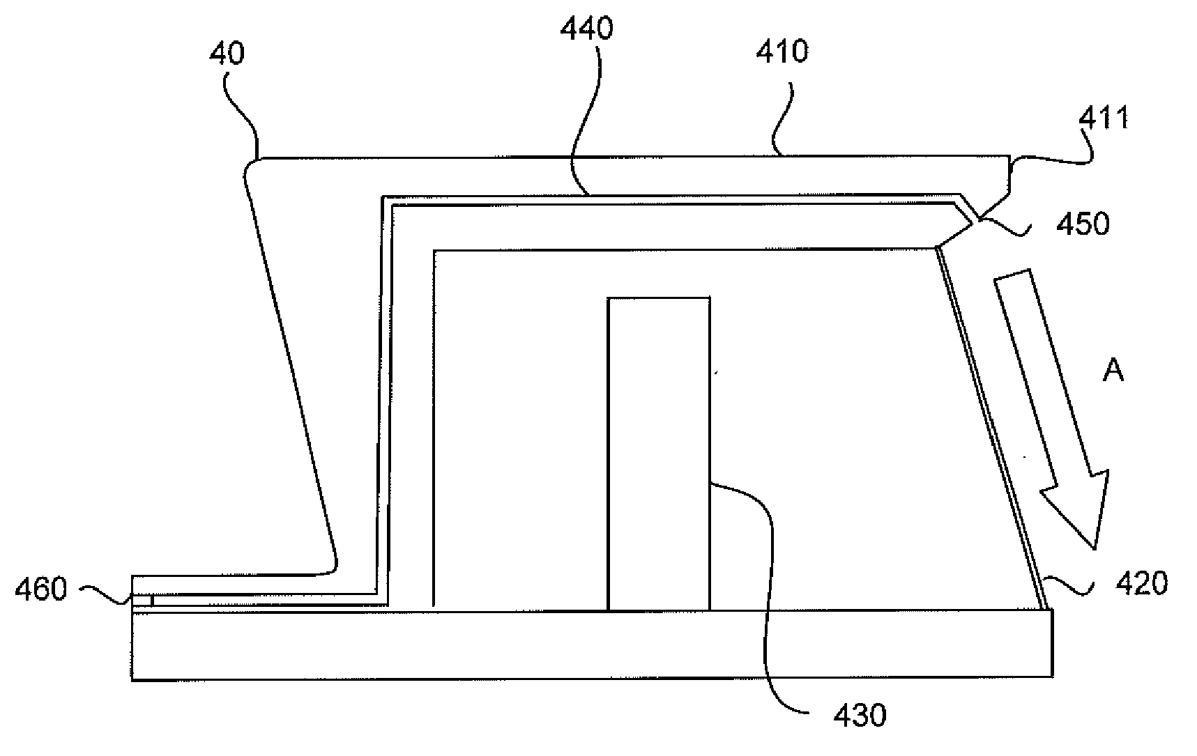
A milking system includes a milking robot with a robot arm for applying teat cups to the teats of an animal, an optical detector (40) for detecting radiation emitted and / or reflected from the animal and a controller. The detector has a housing (410) with a window (420) and a detecting element (430) enclosed in the housing that is sensitive to the emitted or reflected radiation passing through the window. In order to prevent contamination from impacting on the detector window, an airflow arrangement is provided that can be connected to a source of pressurized air and has at least one aperture (411) disposed adjacent the detector window (420) for generating a curtain of air that flows parallel with the surface of the window. The controller controls the generation of the air curtain to coincide with the start of at least one further operation controlled by the controller.

Description

technical field [0001] The present invention relates to optical detectors for use in contaminated environments, and is of particular relevance to optical detectors used in automatic or semi-automatic milking systems, eg for determining the position of an animal's teat. Background technique [0002] Optical detection arrangements, such as those commonly used in automatic milking systems, typically include a detector in the form of a diode detector or a CCD array camera for detecting and use the detected radiation to determine the distance between the object and the detector. Some systems may also have a radiation source, such as a laser, used to irradiate the subject of interest with suitable radiation. In most cases, the radiation detector and radiation source, if present, are arranged in the housing behind a screen or window that protects the camera or diode from the environment. The window may be made of glass or other suitable transparent material through which visible ...

Claims


Application Information

Patent Timeline
Patent Type & Authority Applications(China)
IPC IPC(8): A01J5/017
CPCA01J5/0175
Inventor 贾恩·埃瑞克·安德松安德斯·哈尔斯特伦
Owner DELAVAL HLDG AB
Why Eureka
Try Eureka