
Optical transceiver component and optical module

A technology for light-emitting components and optical components, applied in the field of electronics, can solve problems such as crosstalk, and achieve the effects of reduced crosstalk, great significance, and reduced chip size

Active Publication Date: 2015-12-09
HUAWEI TECH CO LTD
View PDF6 Cites 0 Cited by
  • Summary
  • Abstract
  • Description
  • Claims
  • Application Information

AI Technical Summary

Problems solved by technology

[0005] In order to solve the problem of crosstalk between the optical signal sent by the transmitting device and the receiving device in the prior art, the embodiment of the present invention provides a transceiver optical component and an optical module

Method used


Image

  • Optical transceiver component and optical module
  • Optical transceiver component and optical module
  • Optical transceiver component and optical module

Examples


Embodiment 2

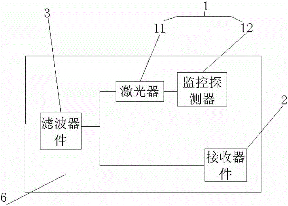
[0046] Such as image 3 As shown, a top view of a light-receiving assembly provided by an embodiment of the present invention.

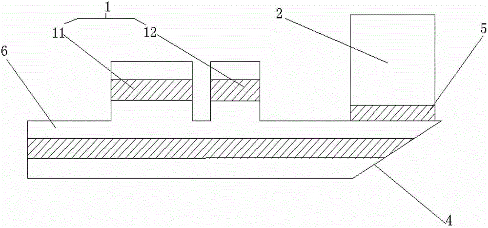
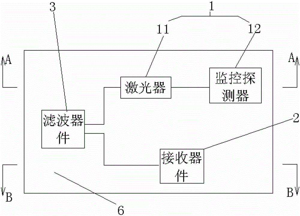
[0047] Such as Figure 4 As shown, an embodiment of the present invention provides a light-receiving assembly, the light-receiving assembly includes: a transmitting device 1, a receiving device (see image 3 ) And filter components (see image 3 ), the emitting device 1 includes a laser 11 and a monitoring detector 12, the laser 11 and the filter device (see image 3 ) Are integrated in the same chip 6, the monitoring detector 12 and the receiving device (see image 3 ) Fixed at the outer surface of the chip 6;

[0048] On the one hand, the transmitting device 1 emits a light signal and passes through the filter device (see image 3 ) Transmit the light signal to the outside; on the other hand, it receives the light signal from the outside and passes through the filter device (see image 3 ) Reflect this optical signal into the receiving device (see image ...


PUM


Abstract

Disclosed are a transmitting-receiving optical component and an optical module. The transmitting-receiving optical component comprises a transmitting device, a receiving device and a filter device, wherein the transmitting device and the filter device are integrated into the same chip and the receiving device is fixed on the outer surface of the chip; on one aspect, the transmitting device transmits an optical signal and sends the optical signal to the outside via the filter device; and on the other aspect, the transmitting device receives an optical signal transmitted from the outside and reflects the optical signal into the receiving device via the filter device. The optical module is provided with the transmitting-receiving optical component. According to the present invention, a receiving device is arranged externally on the outer surface of a chip, while a transmitting device is integrated into the chip, so that the possibility that an optical signal may generate crosstalk to the receiving device is reduced greatly, thereby reducing or even eliminating the influence of the receiving device on the receiving performance of other optical signals. Moreover, the present invention is simple in structure, the size of the chip is decreased and the cost is reduced.

Description

Technical field [0001] The invention relates to the field of electronics, in particular to a light-receiving component and an optical module. Background technique [0002] Passive optical network PON (passive optical network) technology has become the most favored solution for operators in the field of optical fiber access FTTx (FiberToTheX) by virtue of its point-to-multipoint network architecture and passive advantages. But the large-scale deployment of PON technology is directly restricted by the cost of active optical components. The commonly used active optical component is a kind of light-receiving component, which mainly includes: transmitting device, receiving device, filter device. On the one hand, the transmitting device emits light signal, and the light signal is transmitted to the outside through the filter device, and on the other hand, it receives the outside world. The transmitted optical signal is reflected by the filter into the receiving device, and the receivi...

Claims


Application Information

Patent Timeline
Patent Type & Authority Patents(China)
IPC IPC(8): H04B10/40
CPCG02B6/4214
Inventor 周小平董英华程宁凌魏
Owner HUAWEI TECH CO LTD
Learn More