
Interlocking structure of automobile braking system

An automobile braking system and interlocking technology, which is applied to control devices, vehicle components, foot start devices, etc., can solve problems such as different technical effects, and achieve the effects of reducing driving steps, convenient installation and adjustment, and intuitive and clear functions.

Inactive Publication Date: 2013-08-07
JIANGXI B ENERGY SHANGRAO COACH
View PDF6 Cites 47 Cited by
  • Summary
  • Abstract
  • Description
  • Claims
  • Application Information

AI Technical Summary

Benefits of technology

Inventions have been developed into new types of automatic car security features called InterLockings (I). These improvements make sure they work properly even if someone tries to drive them wrongly due to any issues like lack of power supply or insufficient gearboxes. They allow the car to stop safely when needed while still being able to operate normally. Additionally, these improved designs simplify assembly processes and reduce costs compared to existing solutions such as hydraulic shock absorption mechanisms. Overall, I provide technical benefits including enhanced efficiency, reliability, ease of maintenance, reduced risk of accidents caused by incorrect operations, increased comfort levels for passengers, better control over steering wheel movements, safer driving behavior, and more efficient energy management practice than current methods.

Problems solved by technology

The technical problem addressed in this patents relates to improving the ease of manually shifting between gears without increasing costs or reducing their overall performance compared to older designs.

Method used


Image

  • Interlocking structure of automobile braking system

Examples


Embodiment Construction

[0039] In order to describe the technical content of the present invention more clearly, further description will be given below in conjunction with specific embodiments.

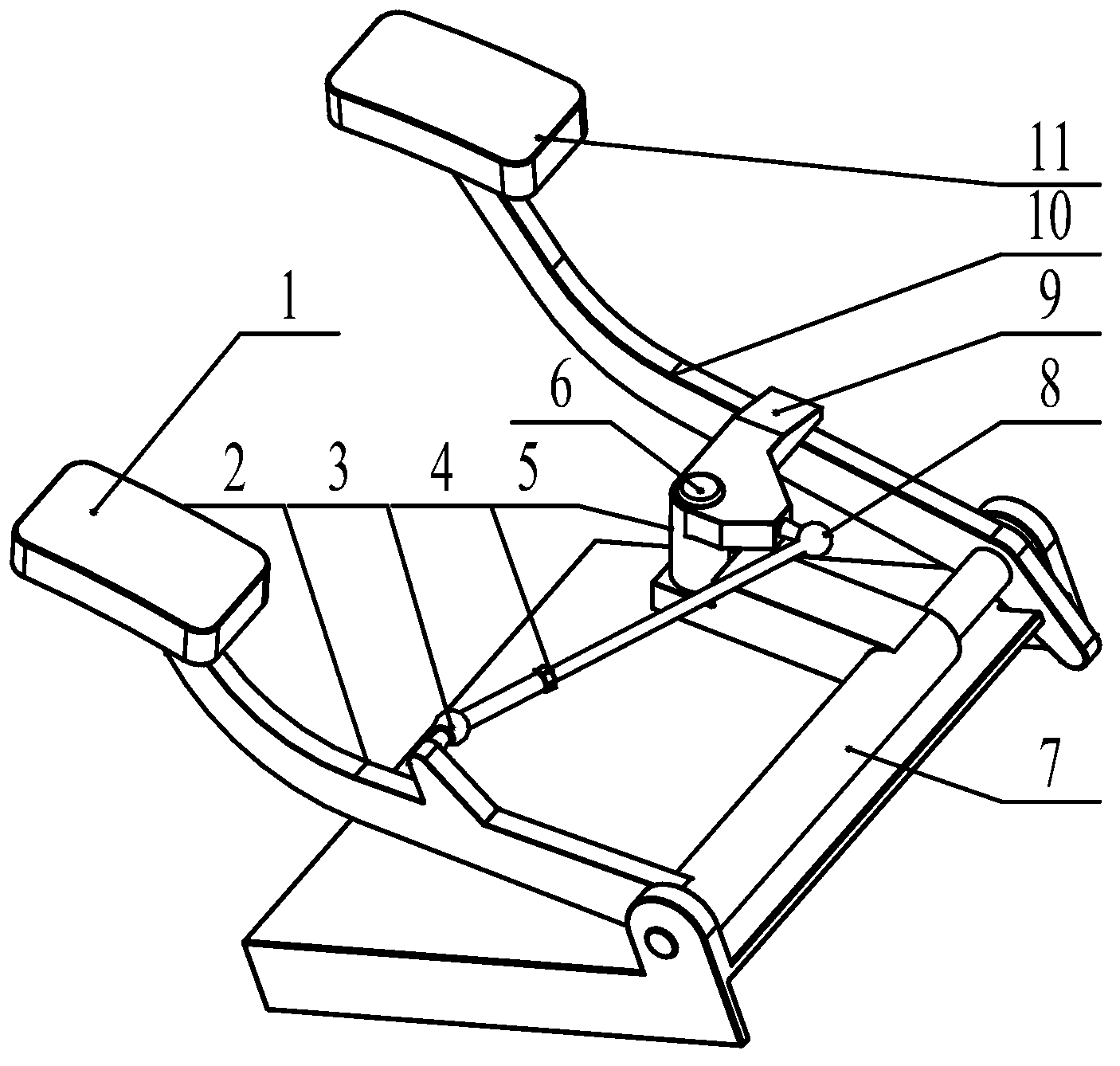
[0040] Such as figure 1 As shown, it is a structural schematic diagram of the interlocking structure of the automobile brake system in the first embodiment.

[0041] The interlocking structure of the automobile brake system is that a space-moving link linkage mechanism is set between the brake pedal and the clutch pedal of the automobile.

[0042] The structure includes a brake pedal lever 2 connected with the brake pedal 1 of the automobile, a kinematic link 4 as a chain transmission mechanism, a swing arm 5, a claw 9 as a pressing part, a sleeve Pipe 7 and a clutch pedal lever 10 connected with the clutch pedal of the car.

[0043] One end of the moving link 4 is hinged on the inner side of the brake pedal lever 2 through the first ball joint 3, and the other end of the moving link 4 is hinged on the in...


PUM


Abstract

The invention relates to an interlocking structure of an automobile braking system. The interlocking structure of the automobile braking system comprises a brake pedal lever, a clutch pedal lever, an interlocking transmission mechanism and an interlocking actuator, wherein the interlocking transmission mechanism is movably connected with the brake pedal lever, the interlocking actuator is movably connected with the interlocking transmission mechanism, the interlocking actuator moves away from or close to the clutch pedal lever under the control of the interlocking transmission mechanism, and the interlocking actuator adjusts the position of the clutch pedal lever through the relative motion with the clutch pedal lever. By utilizing the interlocking structure of the automobile braking system of the above structure, the united braking of an automobile brake and a clutch during emergency braking can be achieved, the operating procedure of the emergency braking can be simplified, and the normal driving operation of an automobile is not affected. Besides, the interlocking structure of the automobile braking system is simple in structure, easy to disassemble and assemble, convenient to use, safe and reliable and has a wider application range.

Description


Claims


Application Information

Patent Timeline
Owner JIANGXI B ENERGY SHANGRAO COACH
Learn More