
A fracturing sand mixing device

A technology of sand mixing and fracturing, which is applied in the direction of production fluid, wellbore/well components, earthwork drilling and production, etc. It can solve the problems affecting the normal production of oil and gas fields, difficult to predict the reverse flow effect, and long time for fracturing fluid flow back, etc. question

Active Publication Date: 2015-12-23
YANTAI JEREH OILFIELD SERVICES GROUP
View PDF9 Cites 112 Cited by
  • Summary
  • Abstract
  • Description
  • Claims
  • Application Information

AI Technical Summary

Problems solved by technology

[0004] At present, water-based or oil-based fracturing fluids are commonly used in traditional fracturing processes to fracture oil or gas layers, but there are certain defects in using water-based or oil-based fracturing fluids for fracturing operations: first , the water-based or oil-based fracturing fluid will cause damage to the reservoir after degradation, especially the impurities produced by the degradation will cause damage to the capillary pores around the fractures of the reservoir
Secondly, after the fracturing is completed, the water-based or oil-based fracturing fluid takes a long time to flow back, and the flow-back effect is difficult to predict, which affects the normal production of oil and gas fields
In order to avoid the above problems, people use liquid carbon dioxide or liquefied petroleum gas (propane) as the base fluid of fracturing fluid, but carbon dioxide or petroleum gas (propane) can only exist in a liquid state under a certain pressure, while the existing Sand mixing device suitable for water-based or oil-based fracturing fluid (used to mix solid and liquid raw materials to make fracturing fluid). Since the fracturing fluid does not need to exist in a high-pressure environment, its accommodation space is open It is not suitable for the preparation of fracturing fluids with liquid carbon dioxide or liquefied petroleum gas (propane) as the base fluid

Method used


Image

  • A fracturing sand mixing device

Examples


Embodiment Construction

[0024] The invention provides a fracturing sand mixing device, which is suitable for the preparation of fracturing fluid with liquid carbon dioxide or liquefied petroleum gas (propane) as the base fluid.

[0025] The following will clearly and completely describe the technical solutions in the embodiments of the present invention with reference to the accompanying drawings in the embodiments of the present invention. Obviously, the described embodiments are only some, not all, embodiments of the present invention. Based on the embodiments of the present invention, all other embodiments obtained by persons of ordinary skill in the art without making creative efforts belong to the protection scope of the present invention.

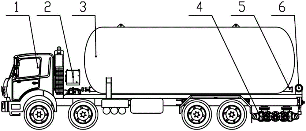
[0026] Such as figure 1 As shown, the fracturing sand mixing device provided by the embodiment of the present invention is used for mixing fracturing fluid, such as fracturing fluid with liquid carbon dioxide or liquefied petroleum gas (propane) as the base ...


PUM


Abstract

The invention provides a fracturing sand mixing device used for mixing fracturing fluid. The fracturing sand mixing device comprises a solid conveying device and a solid-liquid mixing device communicated with the solid conveying device, wherein the solid-liquid mixing device is a pressure container. The solid-liquid mixing device comprises a solid lead-in port capable of leading in solid particles of the fracturing fluid output by the solid conveying device, a base fluid lead-in port for leading in base fluid of the fracturing fluid, a mixing inner cavity for accommodating the solid particles and the base fluid and a solid-liquid lead-out port for leading out the fracturing fluid formed by mixing. Substances such as carbon dioxide or petroleum gas which are in a gas state under normal temperature can be kept in a liquid state by high pressure through the fracturing sand mixing device and are mixed with the solid particles to form the fracturing fluid, and the goal of preparing the fracturing fluid with liquid carbon dioxide or liquefied petroleum gas (propane) serving as the base fluid is achieved.

Description

technical field [0001] The invention relates to the technical field of oil / gas production equipment, more specifically, to a fracturing sand mixing device. Background technique [0002] During oil testing or production of oil and gas wells, the production of oil and gas wells will be low due to pollution near the wellbore (drilling, cementing, well washing and killing processes will cause pollution) or low original permeability of the formation. This problem can be solved by fracturing technology. [0003] Fracturing technology refers to a method of using liquid pressure to form cracks in oil and gas reservoirs in the process of oil or gas production. The specific operation is to use high-pressure and large-displacement pumps and use the principle of liquid pressure transmission. A liquid with a certain viscosity (that is, fracturing fluid) is injected into the reservoir at a pressure greater than the absorption capacity of the reservoir, and the pressure in the wellbore is...

Claims


Application Information

Patent Timeline
Patent Type & Authority Patents(China)
IPC IPC(8): E21B43/26
Inventor 崔日哲王峰刘合吕亮刘东韩增平李守哲张海波张怀智杜明强
Owner YANTAI JEREH OILFIELD SERVICES GROUP
Learn More