
Filling material guiding mechanism of solid filling conveying machine

A technology of solid filling and conveying machine, which is applied to filling materials, safety devices, mining equipment, etc., can solve the problems that the compaction mechanism is difficult to compact quickly, affects the efficiency of coal mining, and prolongs the mining time, so as to improve the efficiency of filling work, Improve the filling effect and increase the effect of stacking space

Inactive Publication Date: 2013-08-07
CHINA UNIV OF MINING & TECH
View PDF6 Cites 0 Cited by
  • Summary
  • Abstract
  • Description
  • Claims
  • Application Information

AI Technical Summary

Problems solved by technology

Since the position of the discharge hole cannot be adjusted, the solid filling material passing through the discharge hole can only be stacked at a fixed position under the discharge hole of the coal mining filling conveyor, and the solid filling material will pass through the solid filling and coal mining integrated hydraulic support. Compaction by the compaction mechanism. Although this mechanism realizes the filling and compaction of solid filling materials in the goaf, it is difficult for the compaction mechanism to achieve rapid compaction in actual use, resulting in prolonged mining time and significantly affecting coal mining efficiency.

Method used


Image

  • Filling material guiding mechanism of solid filling conveying machine
  • Filling material guiding mechanism of solid filling conveying machine
  • Filling material guiding mechanism of solid filling conveying machine

Examples


Embodiment Construction

[0014] An embodiment of the present invention will be further described below in conjunction with accompanying drawing:

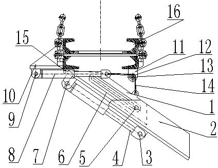
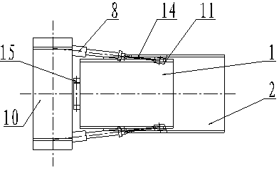
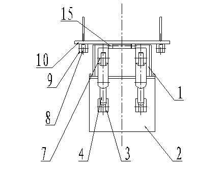
[0015] Such as figure 1 As shown, the filling guide mechanism of the solid filling conveyor of the present invention is mainly composed of an inner tank 1, an outer tank 2, an inclined hydraulic jack 4, a horizontal hydraulic jack 8, a fixed steel plate 10, and a pulley 12. The fixed steel plate 10 is designed On the outer side of the lower side of the discharge port of the filling conveyor 16, the pulley 12 is arranged on the side of the inner side of the filling coal mining conveyor 16, and the pulley 12 is fixed on the front connecting seat 11 through the pulley pin shaft 13. The horizontal hydraulic pressure Jack 8 is located on the bottom of fixed steel plate 10 through horizontal hydraulic jack fixed pin 9, and the horizontal hydraulic jack 8 that steel plate 10 bottoms is provided with is two, symmetrically arranged. Below the horizontal hydraulic j...


PUM


Abstract

A filling material guiding mechanism of a solid filling conveying machine mainly comprises an inner groove, an outer groove, an inclined hydraulic jack, a slide, a horizontal hydraulic jack, a fixed steel plate, a front connecting base, a pulley and a material guiding groove rotary shaft. The front connecting base and the material guiding groove rotary shaft are fixed below a filling conveying machine discharging port through welding. The horizontal hydraulic jack is connected with the inner groove through a steel wire rope and the pulley, and the inner groove is connected with the outer groove through a sliding pin shaft and the slide. By means of extending and retracting of the horizontal hydraulic jack, rotation of the inner groove and the outer groove around the material guiding groove rotary shaft is achieved. One end of the inclined hydraulic jack is connected with the inner groove, the other end of the inclined hydraulic jack is connected with the outer groove, and extending and retracting of the outer groove are achieved through extending and retracting of the inclined hydraulic jack. By means of rotation and extending and retracting of the material guiding mechanism, adjusting of a discharged material piling position of a solid filling material is achieved according to filling requirements, a filling procedure is simplified, and filling working efficiency and filling effect are greatly improved.

Description

technical field [0001] The invention relates to a solid filling mechanism, in particular to a filling and guiding mechanism suitable for comprehensive mechanized solid filling coal mining conveyors in mines. technical background [0002] Due to the rapid growth of coal production in my country in recent years, coupled with the unreasonable distribution of coal resources and poor mining conditions, especially the coal resources of most mines in the east are close to depletion, and most of them have been "three downs" (under the railway, under the water body, under the water, etc.) under the building) to press coal. With the progress of the underground coal mining face, the original stress balance state inside the overlying strata is destroyed, and the stress redistribution occurs inside the strata, which causes the overlying strata in the stope to collapse, break, separate, move and deform, and eventually lead to Large-scale surface subsidence, migration of groundwater, damag...

Claims


Application Information

Patent Timeline
IPC IPC(8): E21F15/06
Inventor 周跃进缪协兴刘玉徐平周永臣彭刚郁邦永曹正正
Owner CHINA UNIV OF MINING & TECH
Features
  • Generate Ideas
  • Intellectual Property
  • Life Sciences
  • Materials
  • Tech Scout
  • Unparalleled Data Quality
  • Higher Quality Content
  • 60% Fewer Hallucinations
Learn More