Method for measuring circular polarization antenna axial ratio by utilizing linear polarization antenna

A technology of circularly polarized antennas and polarized antennas, which is applied in the directions of antenna radiation patterns, can solve the problems that circularly polarized antennas are not easy to manufacture, cannot completely eliminate changes in amplitude and phase, and test errors, and it is easy to achieve polarization directions Determine, reduce the influence of uncontrollable factors, reduce the effect of measurement time

Inactive Publication Date: 2013-08-07
NORTHWESTERN POLYTECHNICAL UNIV
View PDF4 Cites 15 Cited by
  • Summary
  • Abstract
  • Description
  • Claims
  • Application Information

AI Technical Summary

Problems solved by technology

However, because the rotary joint of the polarization turntable cannot completely eliminate the amplitude and phase changes caused by the cable jitter caused by the rotation, especially in the high frequency band, this phenomenon is particularly obvious, which will bring errors to the test
At the same time, because the standard circularly polarized antenna is not easy to manufacture, the circularly polarized antenna is usually not used as an auxiliary antenna for accurate measurement

Method used


Image

  • Method for measuring circular polarization antenna axial ratio by utilizing linear polarization antenna
  • Method for measuring circular polarization antenna axial ratio by utilizing linear polarization antenna
  • Method for measuring circular polarization antenna axial ratio by utilizing linear polarization antenna

Examples


Embodiment Construction

[0017] Now in conjunction with embodiment, accompanying drawing, the present invention will be further described:

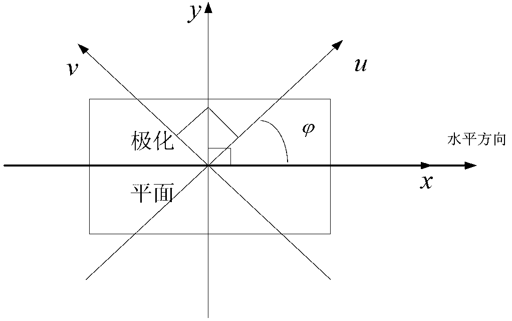
[0018] A polarization ellipse can be represented by any orthogonal coordinate system, that is, it can be decomposed orthogonally. We use the linear polarization component method to decompose the polarization ellipse orthogonally. Here we use two sets of orthogonal linear polarization components for testing.

[0019] In this embodiment, a circularly polarized antenna is used as the antenna to be tested, which can rotate in the polarization plane, and a linearly polarized pyramidal horn antenna with precise scale is used as the auxiliary antenna, and the test frequency is 8.5 GHz.

[0020] Test operation:

[0021] 1) In the darkroom, select a linearly polarized antenna whose polarization direction is known as the auxiliary antenna, and make the polarization state of the linearly polarized antenna the same as the four polarization directions of x, y, u, and v in tu...


PUM


Abstract

The invention relates to a method for measuring a circular polarization antenna axial ratio by utilizing a linear polarization antenna. The method is characterized in that the linear polarization antenna with a known polarization direction is selected to be an auxiliary antenna in a microwave unreflected chamber, polarization states of the linear polarization antenna are sequentially enabled to be the same with four polarization directions of x, y, u and v, the antenna directional graph measuring is carried out on a to-be-measured circular polarization antenna in four polarization states of the auxiliary antenna, radiation values of Ex (theta), Ey (theta), Eu (theta), Ev (theta) of the to-be-measured antenna are obtained, an inclination angle of the to-be-measured circular antenna is calculated, and an axial ratio AR (theta) of the to-be-measured polarization antenna is obtained. According to the method, a linear polarized horn antenna is adopted to be the auxiliary antenna, the polarization direction of the linear polarized horn antenna is easily determined, the measuring time is reduced, and the test difficulty is lowered; and the auxiliary antenna is in a static state, so that the affects from uncontrollable factors are reduced, and the obtained information of the circular polarization antenna axial ratio is enabled to be realer and more reliable.

Description

technical field [0001] The invention belongs to the field of antenna testing, and in particular relates to a method for measuring the axial ratio of a circularly polarized antenna by using a linearly polarized antenna. Background technique [0002] In the circularly polarized antenna test, it is necessary to measure the axial ratio of the circularly polarized antenna to judge whether the degree of circular polarization of the circularly polarized antenna meets the design requirements. The rotating source method uses a linearly polarized antenna that can rotate rapidly in the same polarization plane as an auxiliary antenna, and at the same time adjusts the azimuth turntable where the circularly polarized antenna to be tested to an appropriate speed, so that a more realistic axial ratio can be obtained. information. However, because the rotary joint of the polarization turntable cannot completely eliminate the amplitude and phase changes caused by the cable jitter caused by t...

Claims


Application Information

Patent Timeline
Patent Type & Authority Applications(China)
IPC IPC(8): G01R29/10
Inventor 李南京冯引良王剑飞李瑛刘宁杨博陈卫军刘琦郭淑霞
Owner NORTHWESTERN POLYTECHNICAL UNIV
Why Eureka
Try Eureka