Sintering mold and sintering method of diode with square lead

A square and diode technology, which is applied in the sintering mold and sintering field of diodes, can solve problems such as the inability to maintain the upper and lower flatness of the square leads, exposure, and inconsistent process regulations, etc., and achieve the effect of improving operability and good sealing performance

Active Publication Date: 2013-08-07
JINAN JINGHENG ELECTRONICS
View PDF5 Cites 6 Cited by
  • Summary
  • Abstract
  • Description
  • Claims
  • Application Information

AI Technical Summary

Problems solved by technology

[0003] Currently existing diode sintering molds adopt axial positioning for diodes. Firstly, the up and down flatness of the square lead wires cannot be maintained, which is inconsistent with the process regulat

Method used


Image

  • Sintering mold and sintering method of diode with square lead
  • Sintering mold and sintering method of diode with square lead

Examples


Embodiment Construction

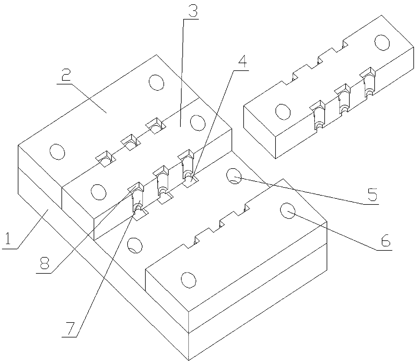
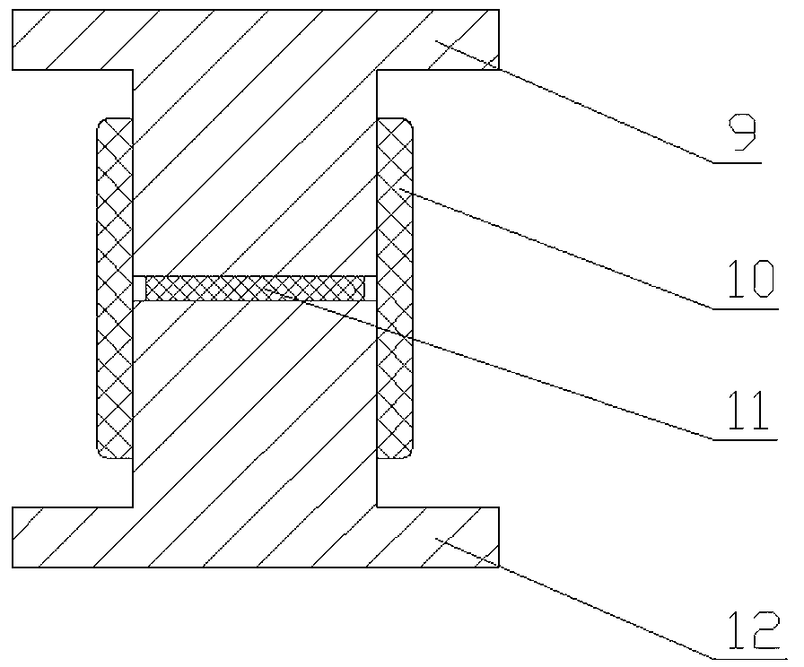
[0015] like figure 1 As shown, the sintering mold includes a base 1 and an upper positioning block. Two rows of diode cavities are arranged on the base and the upper positioning block. Each row has a plurality of diode cavities, and the diode cavities include lower rectangular grooves 4 connected in sequence. , The second-level stepped cylindrical hole 7 and the upper rectangular groove 8, the lower rectangular groove 4 is arranged on the base 1, the lower rectangular groove 4 matches the terminal of the lower square lead wire, and the matching means that the terminal of the lower square lead wire is exactly Can be put into the lower rectangular groove 4. Both the secondary stepped cylindrical hole 7 and the upper rectangular groove 8 are arranged on the upper positioning block, the small end of the secondary stepped cylindrical hole 7 faces downward, and the secondary stepped cylindrical hole 7 is connected with the glass bulb 10 and the lower part exposed outside the glass ...


PUM


Abstract

The invention discloses a sintering mold and a sintering method of a diode with square lead. The sintering mold comprises a base and an upper location block, wherein at least one diode mold cavity is formed in the base and the upper location block; the diode mold cavity comprises lower rectangular grooves, two-step cylindrical holes, and upper rectangular grooves, which are communicated with each other in sequence; the lower rectangular grooves are formed in the base; the lower rectangular grooves are matched with a connection terminal of a lower square lead; the two-step cylindrical holes are matched with a glass casing, and a cylindrical electrode of the lower square lead exposed out of the glass casing; and the upper rectangular grooves are used for accommodating an upper square lead exposed out of the glass casing. The sintering method provided by the invention adopts the abovementioned sintering mold. The mold provided by the invention can ensure that the two cylindrical electrodes exposed out of the glass casing are substantially identical in length, so that the sintered diode has good sealing performance.

Description

technical field [0001] The invention relates to a sintering mold and a sintering method of a diode, in particular to a sintering mold and a sintering method of a diode with square leads. Background technique [0002] like figure 2 As shown, the diode of the square lead includes an upper square lead 9, a glass bulb 10, a chip 11 and a lower square lead 12, the glass bulb 10 is a round glass tube, and the two square leads include cylindrical electrodes and are arranged in a direction perpendicular to the diode axis. The section of the terminal is a square terminal, the side length of the square is longer than the diameter of the glass bulb 10, the cylindrical electrode is fixed at the center of the terminal, the chip 11 is in the glass bulb 10, and the cylindrical electrodes of the two square lead wires are respectively inserted into the glass bulb 10 The two ends of the chip 11 are in contact with the chip 11. The total length of the chip 11 and the two cylindrical electrod...

Claims


Application Information

Patent Timeline
IPC IPC(8): H01L21/68H01L21/50H01L21/67
Inventor 王培祥戚涛邵亦军孙菲朱海涛
Owner JINAN JINGHENG ELECTRONICS
Why Eureka
Try Eureka