LED with luminous front and rear sides

An LED chip, double-sided technology, applied to LEDs. It can solve the problems of luminous efficiency loss, unidirectional light emission from the packaging substrate, and poor flexibility of LED devices, so as to achieve the effect of reducing costs and reducing space.

Inactive Publication Date: 2013-08-07
TIANJIN JINMA PHOTOELECTRIC
View PDF6 Cites 6 Cited by
  • Summary
  • Abstract
  • Description
  • Claims
  • Application Information

AI Technical Summary

Problems solved by technology

[0002] At present, the packaging substrates of LED devices are more commonly used as glass substrates (FR4) and metal substrates (referred to as MCPCB), such as aluminum substrates or copper substrates, and composite substrates. Its function is the basis of LED device packaging, mainly carrying LED circuit, and produce conductive effect, but this kind of packaging substrate can only achieve one-way light output
[0003] In addition, there is a backboard process, which is to add LED light sources on both sides of the acrylic ...

Method used


Image

  • LED with luminous front and rear sides
  • LED with luminous front and rear sides

Examples


Embodiment Construction

[0019] The present invention will be described in further detail below in conjunction with the accompanying drawings and specific embodiments. It should be understood that the specific embodiments described here are only used to explain the present invention, not to limit the present invention.

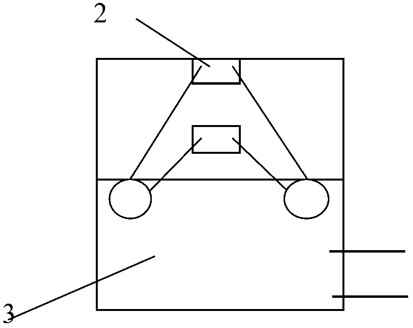
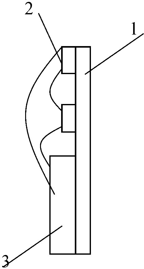
[0020] Such as figure 1 and 2 As shown, a kind of LED that emits light from both front and rear sides includes a glass carrier plate 1 with a thickness of 0.2 mm, and a plurality of LED chips 2 fixedly arranged on the glass carrier plate 1. The substrate of the LED chip is an electroless plated transparent substrate. The LED chips are fixed and arranged on the carrier board through transparent glue. Wherein, the transparent glue is a transparent two-component epoxy resin glue. The glass carrier plate has a light transmission performance of 92%, which can effectively ensure the uniformity of light emitted from both sides.

[0021] On the lower half of the glass carrier, that is, ou...


PUM

PropertyMeasurementUnit
Thicknessaaaaaaaaaa

Abstract

The invention discloses an LED with luminous front and rear sides. The LED comprises a transparent carrier plate, a plurality of LED chips fixed on the transparent carrier plate via scotch tape, and a constant-current temperature controlling circuit board fixedly connected with the transparent carrier plate. Bases of the LED chips are electroless plated transparent bases, and the constant-current temperature controlling circuit board is communicated with the LED chips. By utilizing the transparent carrier plate and omitting plating layers on sapphire bases of the LED chips, luminous energy of the LED chips is enabled to emit out in a full angle at 360 degrees, so that conversion from horizontal light sources to perpendicular light sources is realized, the limitation of single-side single-direction horizontal light emission at 110 degrees of existing LED lamps is broken, and a tungsten filament suspension effect is realized.

Description

technical field [0001] The invention relates to the technical field of LED lighting, in particular to a direct-viewable LED with light from both front and rear sides. Background technique [0002] At present, the packaging substrates of LED devices are more commonly used as glass substrates (FR4) and metal substrates (referred to as MCPCB), such as aluminum substrates or copper substrates, and composite substrates. Its function is the basis of LED device packaging, mainly carrying It touches the LED circuit and produces electrical conductivity, but this kind of packaging substrate can only emit light in one direction. [0003] In addition, there is a backboard process, which is to add LED light sources on both sides of the acrylic board. The LED light source is fixed on the surface of the glass board by SMD technology, and then combined with the acrylic board. The acrylic The surface of the board has been printed with white dots, so the LED light source is refracted through...

Claims


Application Information

Patent Timeline
IPC IPC(8): H01L25/13H01L33/48H01L33/64
CPCH01L2224/48091H01L2224/49113H01L2924/13091H01L2924/00014H01L2924/00
Inventor 张荣民田景明
Owner TIANJIN JINMA PHOTOELECTRIC
Why Eureka
Try Eureka