Integrated measuring device for multiple-point type flow velocity pressure temperature

A measuring device, multi-point technology, applied in the direction of measuring device, temperature measurement of moving fluid, pressure difference measurement between multiple valves, etc. The location is difficult to meet and other problems, to achieve the effect of achieving multi-point pressure averaging, reducing operation and maintenance costs, and ensuring accuracy

Active Publication Date: 2013-04-10
南京吉纳波环境测控有限公司
View PDF6 Cites 15 Cited by
  • Summary
  • Abstract
  • Description
  • Claims
  • Application Information

AI Technical Summary

Problems solved by technology

However, due to site constraints at the site of the pollution source, the straight pipe section of the flue is short, and the installation location is difficult to meet the requirements of GB / T 16157-1996. The flow field inside the flue has uneven distribution of flow velocity, and there are high, medium, and low Velocity area, so single-point measurement is difficult to represent the true flow velocity of the flue section
Chinese Patent Publication No. CN201408201Y, a pitot tube device suitable for short flue flue gas velocity measurement, the device discloses as figure 1 As shown, the device is composed of several pitot tube probes, a pressure equalization damper, a total dynamic pressure tube 5, and a total static pressure tube 6. The pressure equalization damper is divided into a dynamic pressure mixing zone 3 and a static pressure mixing zone 4. The dynamic pressure tubes 1 of the pitot tube probes are respectively connected to the dynamic pressure inlets of the dynamic pressure mixing zone of the pressure equalizing damper, and the static pressure tubes 2 of the pitot tube probes are respectively connected to the static pressure mixing zones of the pressure equalizing damper. The air inlets of the static pressure pipes in each static pressure mixing zone are connected, the total dynamic pressure pipe 5 is connected to the dynamic pressure air outlet of the pressure equalization damper, the total static pressure pipe 6 is connected to the static pressure air outlet of the pressure equalization damper, and the total dynamic pressure The pressure pipe 5 and the total static pressure pipe 6 are respectively connected to the positive and negative ends of the differential pressure transmitter, so as to realize the measurement of the section line flow velocity; but there are also shortcomings: (1) the structure is relatively complicated, and it is inconvenient to install on site; (2) There is no back blowing unit; if timely and effective back blowing is not carried out, the detection hole will be blocked by high-concentration dust if the pitot tube runs for a long time in the flue; (3) If the above-mentioned pitot tube device is equipped with a back blowing device, the overall back blowing , the blowback effect is not good. Due to the long delivery air path, the blowback pressure obtained by each air path is small, and a good blowback effect cannot be achieved; The number of valves will increase the cost of equipment, and the equipment will also become complex and large

Method used


Image

  • Integrated measuring device for multiple-point type flow velocity pressure temperature
  • Integrated measuring device for multiple-point type flow velocity pressure temperature
  • Integrated measuring device for multiple-point type flow velocity pressure temperature

Examples


Embodiment 1

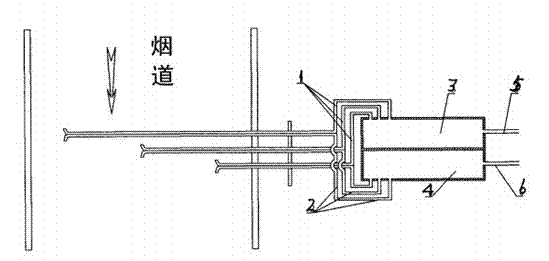
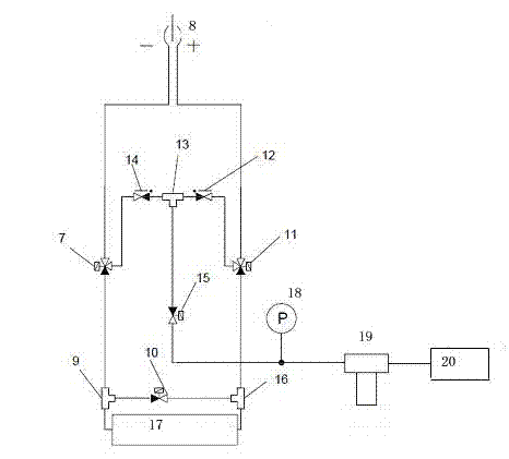
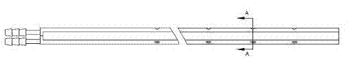
[0033] The multi-point flow rate, pressure and temperature integrated measurement device is composed of a gas path detection unit 8 , a blowback calibration unit and a sensor measurement unit 17 . Such as image 3 and 4 As shown, the gas path detection unit 8 is composed of a porous pitot tube, a mounting flange, and a temperature sensor, and the porous pitot tube is composed of a dynamic pressure tube and a static pressure tube, see image 3 and Figure 4As shown, the dynamic pressure tube 21 is equidistantly provided with 4 concave holes, which can detect the dynamic pressure at different points at the same time. It is a concave hole, facing the direction of flue gas flow, which can eliminate the unevenness of the gas flow direction; the static pressure pipe 22 is located along the flow direction of the flue gas Vs, next to the back of the dynamic pressure pipe 21, and is equally spaced on it. There are 4 sets of static pressure opposite holes, and the two concave holes o...

Embodiment 2

[0043] The material of the porous pitot tube is SS316L, and a more corrosion-resistant anticorrosion layer, such as polytetrafluoroethylene, is sprayed on the outside of the porous pitot tube, and other devices are the same as in embodiment 1.

Embodiment 3

[0045] Such as Figure 5 As shown, the porous pitot tube is composed of a dynamic pressure tube 21 , a static pressure tube 22 , a temperature sensor built-in tube 23 and a heat tracing tube 24 . Among them, the temperature sensor built-in pipe 23 and the heat tracing pipe 24 are respectively located in the concave shape of the two circumscribed circles formed by the dynamic pressure pipe 21 and the static pressure pipe 22, and are close to the dynamic pressure pipe 21 and the static pressure pipe 22; the heat tracing pipe 24 There is a heating material wrapped inside. When the temperature of the smoke is too low, the heating function is activated to prevent the temperature of the smoke from being low. The water in the smoke will appear in the form of water mist and water droplets, which will corrode the Pitot tube. Other devices are with embodiment 1.


PUM


Abstract

The invention discloses an integrated measuring device for multiple-point type flow velocity pressure temperature, and belongs to the technical field of flue gas flow velocity measuring devices. The integrated measuring device for the multiple-point type flow velocity pressure temperature comprises a gas circuit detection unit (8), a backflow calibration unit and a sensing measurement unit (17). An outlet of a dynamic pressure tube of the gas circuit detection unit (8) and an outlet of a static pressure tube of the gas circuit detection unit (8) are respectively connected with an air inlet of the backflow calibration unit. A temperature sensor of the gas circuit detection unit (8) is connected with the sensing measurement unit (17). Through the integrated measuring device for the multiple-point type flow velocity pressure temperature, multi-point measurement on the same pitot tube is achieved, flow velocity of a cross hatching line is directly outputted, accuracy of measurement of fuel gas flow velocity is improved, a gas circuit of a system is shortened, loss of backflow air supply pressure which is caused by the phenomenon that the gas circuit is too long is prevented, the backflow effect is enabled to reach an optimal level, and the gas circuit is prevented from being blocked by dust.

Description

technical field [0001] The invention relates to a flow velocity measuring device for flue gas discharged from a fixed pollution source, in particular to a multi-point flow velocity, pressure and temperature integrated measuring device, which is applied to an online flue gas monitoring system. Background technique [0002] Coal-fired power plants are the main sources of emissions of sulfur dioxide, nitrogen oxides, smoke and greenhouse gas carbon dioxide, etc. The measurement of flue gas emissions is based on the average flue gas flow velocity of the monitoring section, so the accuracy of flow velocity measurement is directly related to the total amount of pollutant emissions. Quantity, concentration calculation and evaluation of the efficiency of the flue gas purification system are important parameters for determining the total amount of pollutant emissions. [0003] At present, there are mainly pitot tube method, ultrasonic method and heat balance method to measure the flu...

Claims


Application Information

Patent Timeline
Patent Type & Authority Applications(China)
IPC IPC(8): G01K13/02G01L9/00G01L13/00G01P5/16G01K13/024
Inventor 刘德允陈清范黎锋陈莹李浙英孙明伟
Owner 南京吉纳波环境测控有限公司
Why Eureka
Try Eureka