Terminal Connection Structure of Stainless Steel Composite Ground Lead

A technology for grounding lead wires and terminals, applied in the direction of connection, conductive connection, clamping/spring connection, etc., can solve the problems that the terminal cannot be disassembled, difficult to connect, inconvenient for test work, etc., achieve fast and convenient connection, and eliminate potential safety hazards , The effect of convenient test work

Active Publication Date: 2015-10-07
CHANGZHOU POWER SUPPLY OF JIANGSU ELECTRIC POWER +3
View PDF8 Cites 0 Cited by
  • Summary
  • Abstract
  • Description
  • Claims
  • Application Information

AI Technical Summary

Problems solved by technology

Although the connection between the terminal and the lead wire is firmly welded, there are some shortcomings. 1. The fastening plate, that is, the terminal is flat, and the terminal is provided with a connection hole connected to the grounding bar of the equipment. The terminal after welding must be It is on the same plane as the grounding bar of external electrical equipment, so the terminal block is directional, which makes it difficult to connect in any direction between the terminal block and the grounding bar of external electrical equipment
2. During the test work, the terminals cannot be disassembled, which brings inconvenience to the test work

Method used


Image

  • Terminal Connection Structure of Stainless Steel Composite Ground Lead
  • Terminal Connection Structure of Stainless Steel Composite Ground Lead
  • Terminal Connection Structure of Stainless Steel Composite Ground Lead

Examples


Embodiment 1

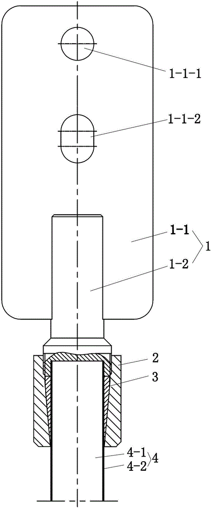
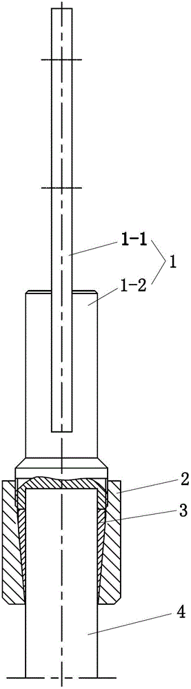
[0018] See Figure 1 to Figure 6 , the present embodiment has lead-in wire 4 and connection terminal 1, lead-in wire 4 is made up of steel mandrel 4-1 and stainless steel sheath 4-2 that tightly wraps its periphery. The terminal 1 is composed of an upper steel rectangular plate 1-1 and a lower steel cylinder 1-2. The steel cylinder 1-2 is stepped, thin at the top and thick at the bottom. A central hole 1-2-1 is provided on the bottom surface of the steel cylinder 1-2. The steel rectangular plate 1-1 of the connecting terminal 1 and the steel The cylinder 1-2 is integral, that is, formed by one-time machining.

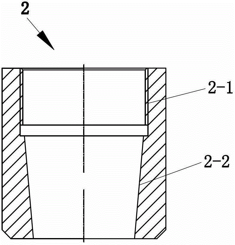
[0019] The connecting terminal 1 is set on the lead wire 4 by using the central hole 1-2-1, the lower part of the steel cylinder 1-2 is provided with an external thread, the internal thread of the nut 2 is arranged on the upper part 2-1 of the inner hole, and the nut The lower part 2-2 of the inner hole has a taper, and a nut 2 sleeved on the lead wire is threadedly c...


PUM


Abstract

The invention relates to a binding post connecting structure for a stainless steel composite material grounding lead-up wire. The binding post connecting structure comprises a lead-up wire and a binding post, wherein the binding post consists of a steel rectangular plate arranged at the upper part and a steel cylinder arranged at the lower part, a center hole is formed in the bottom surface of the steel cylinder, the binding post is sheathed on the lead-up wire through the center hole, external screw threads are arranged on the steel cylinder of the binding post, a screw nut sheathed on the lead-up wire is connected onto the external screw thread part of the steel cylinder of the binding post through screw threads, the lower part of an inner hole of the screw nut has the conical degree, and three grasping claws are arranged between the screw nut and the lead-up wire. The binding post connecting structure has the advantages that the screw nut is used for fixing the lead-up wire and the binding post, the connection can be realized through adopting a general and ordinary tool, the requirement on a construction tool can be reduced, because the threaded connection is adopted, the mounting and the dismounting are convenient, the installation direction of the binding post can be freely changed, the fast and convenient connection with external electric equipment grounding bars in any directions can be realized, in addition, the test work is convenient, and because the three grasping claws are arranged in the screw nut, the connection reliability can be ensured.

Description

technical field [0001] The invention relates to a connection terminal connection structure of a stainless steel composite material ground lead wire. Background technique [0002] The stainless steel composite material ground lead wire is generally rod-shaped. At present, the connection between the lead wire terminal and the ground bar of the external electrical equipment is usually arc welding. The utility model patent of China Authorized Notice No. CN202172131U discloses a conductive connecting plate for lead wires. The conductive connecting plate includes a fastening plate and a connecting pipe for leading wires. There is a notch on the upper end surface of the fastening plate, and the leading wire connecting pipe is inserted into the notch of the fastening plate for welding. Although the connection between the terminal and the lead wire is firmly welded, there are some shortcomings. 1. The fastening plate, that is, the terminal is flat, and the terminal is provided with ...

Claims


Application Information

Patent Timeline
Patent Type & Authority Patents(China)
IPC IPC(8): H01R11/11H01R4/50
CPCH01R4/5091H01R11/11
Inventor 吴鸿飞张劲松马振国周明
Owner CHANGZHOU POWER SUPPLY OF JIANGSU ELECTRIC POWER
Why Eureka
Try Eureka