Biogas system

A biogas and container technology, applied in the field of biogas systems, can solve problems such as unfavorable cap tipping and jamming

Inactive Publication Date: 2013-08-07
SIMGAS IP
View PDF5 Cites 0 Cited by
  • Summary
  • Abstract
  • Description
  • Claims
  • Application Information

AI Technical Summary

Problems solved by technology

Lid tipping is especially bad when the level of digestive mixture inside the bucket rises enough to push a portion of the lid through the top opening

Method used


Image

  • Biogas system
  • Biogas system
  • Biogas system

Examples


Embodiment Construction

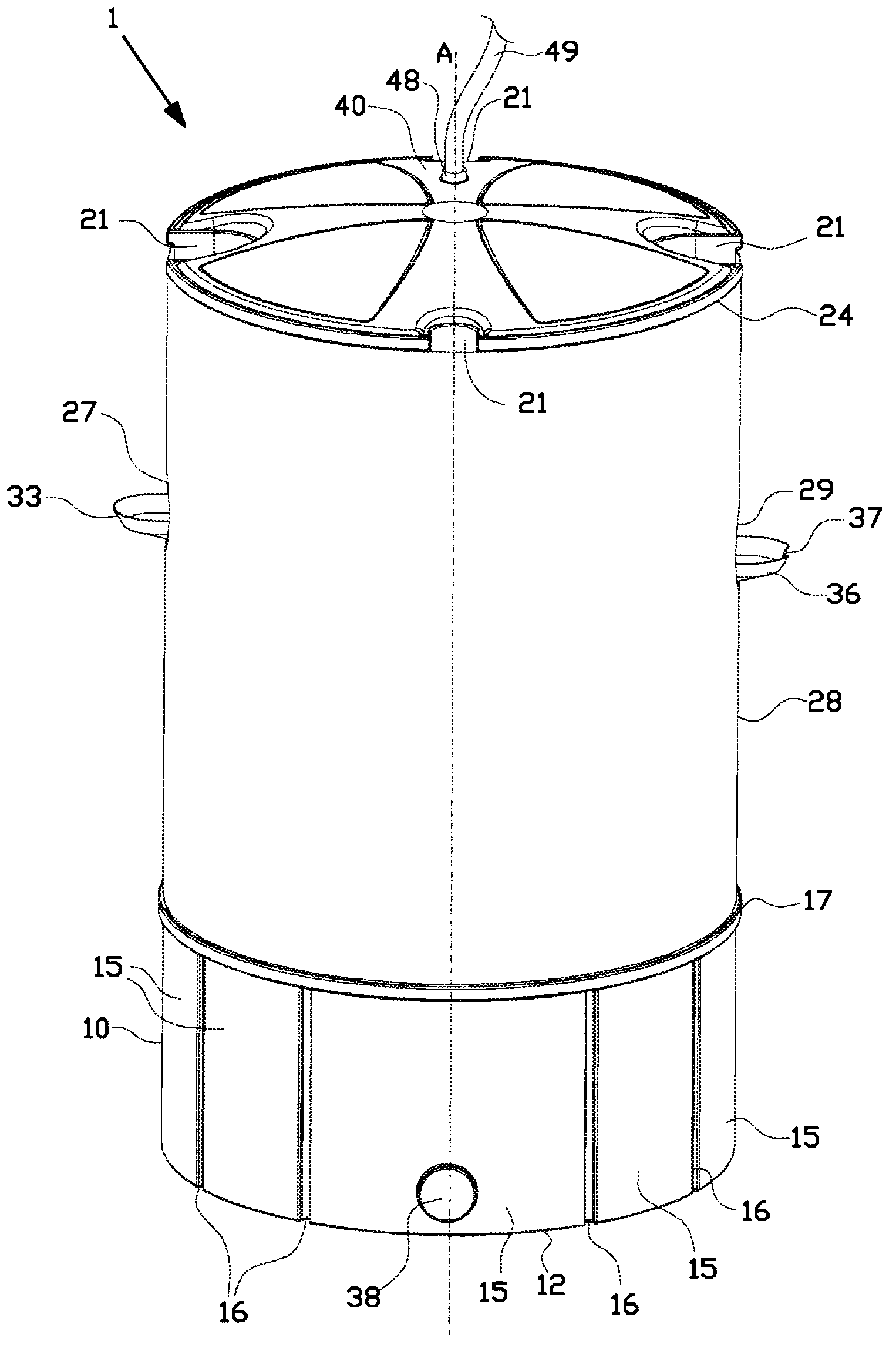
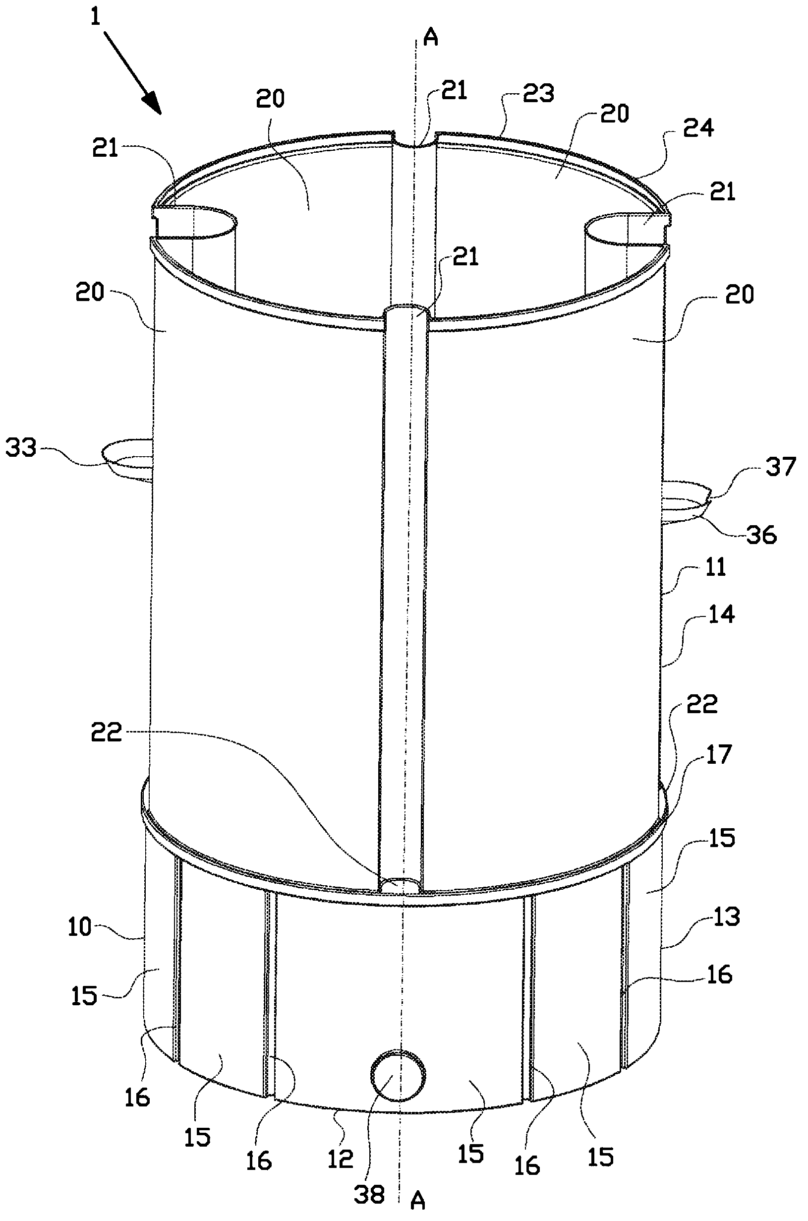
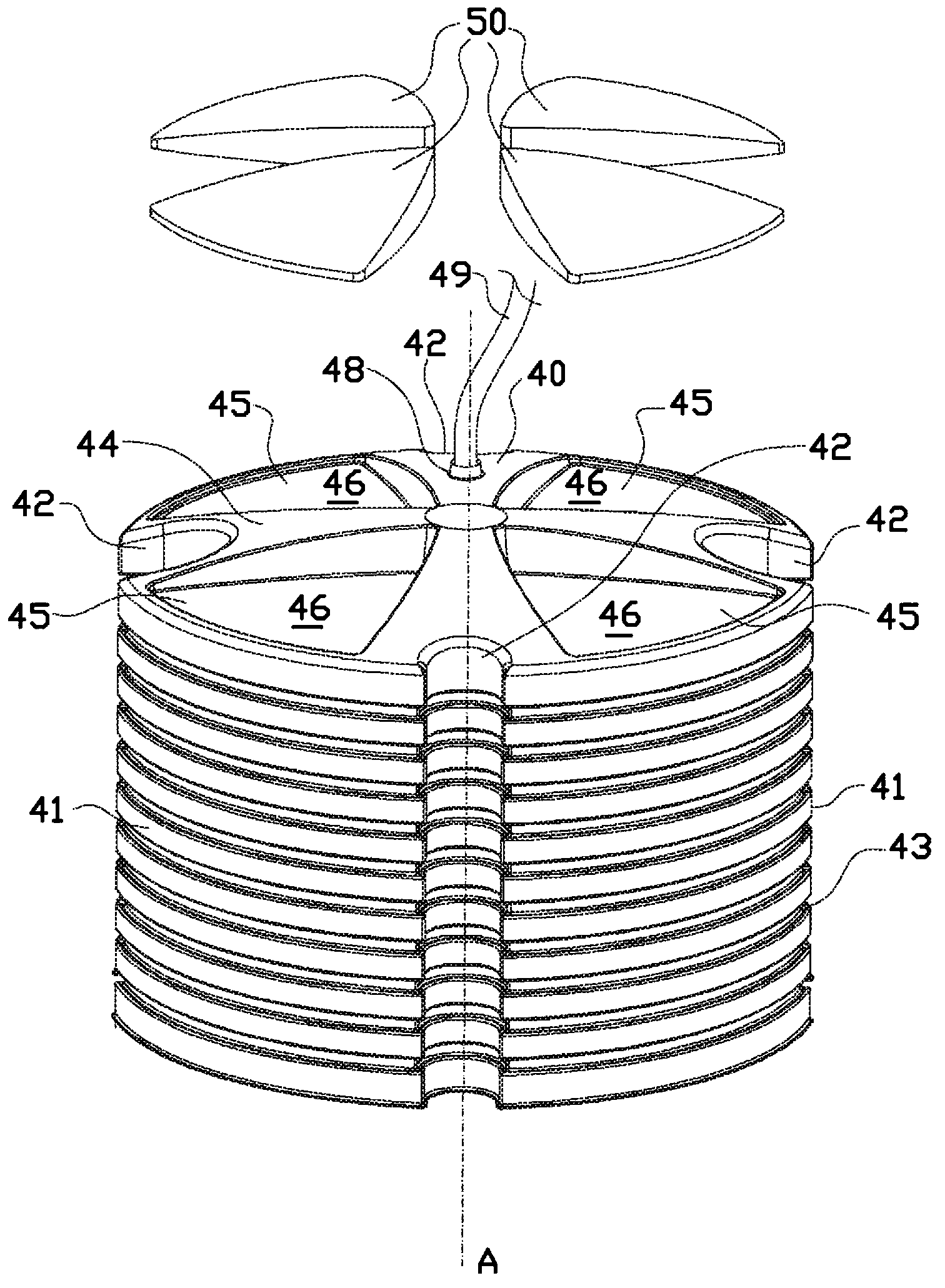
[0049] figure 1 A biogas system 1 according to a first embodiment of the invention is shown. Figure 2A and 2B Some of these components are shown in more detail. The interior of the biogas system 1 consists of Figure 3A and Figure 3B show.

[0050] Such as figure 1 and Figure 2A As shown in , the biogas system 1 comprises a thin-walled digestion vessel 10 comprising a peripheral wall 11 (with a centerline A) and a bottom wall 12, both of which have a constant wall thickness of 4 millimeters at any point. The cylindrical wall 11 defines a digestion chamber 19 and can be roughly divided into a lower slurry section 13 and an upper gas capture section 14 . The digestion vessel 10 is made of a thermoplastic resin such as polyethylene by rotational molding which will be described in detail below.

[0051] At the slurry section 13 , the peripheral wall 11 comprises a first cylindrical wall section 15 which merges into a total of four groups of two concave reinforcing ribs ...


PUM


Abstract

The invention relates to a biogas system comprising a cylindrical digestion vessel having a bottom wall, a first circumferential wall and a top opening to define a digestion chamber filled with a digestive mixture, and a cover having a top side, a second circumferential wall and a bottom opening to define a gas storage chamber, wherein the cover is inserted in the digestion vessel via the top opening with the bottom opening directed towards the bottom wall to capture gas that is released inside the digestion chamber, wherein the digestion vessel comprises first elongated guides and the cover comprises second elongated guides, wherein the first elongated guides are at least partly inserted into the second elongated guides.

Description

technical field [0001] The present invention relates to biogas systems. A biogas system includes a digestion chamber for containing a digested mixture of manure and plants, which is partially dissolved in water to produce methane gas. Methane gas can be used for domestic or small industrial purposes. Background technique [0002] Existing small-scale biogas systems consist of a cylindrical plastic bucket with a top opening over its entire width, and a bucket lid inserted into the bucket through the top opening. The lid floats over the digestion mixture with its opening pointing down so as to capture most of the methane gas. The cap is connected to a gas hose to supply methane gas to the domestic burner. The methane gas is pressurized by stones resting on top of the floating cover. [0003] A disadvantage of the existing small-scale biogas systems is that the floating cover is heavy on the top due to stones, whereby the cover is tilted towards the inside of the bucket to ...

Claims


Application Information

Patent Timeline
IPC IPC(8): C12M1/107B29C41/04
CPCB29C41/04Y02E50/343C12M23/36C12M21/04B29C2793/009Y02E50/30
Inventor 米瑞克·卡斯特罗塞缪尔·卡斯特罗钱德勒·伊丽莎白·哈顿
Owner SIMGAS IP
Why Eureka
Try Eureka