
Control device

A technology of control device and control unit, which is applied in the direction of instrumentation, calculation, analog/digital conversion, etc., can solve the problem of increased load of A/D converter, and achieve the effect of compact structure and simple A/D conversion processing

Inactive Publication Date: 2013-08-07
KEIHIN CORP
View PDF6 Cites 0 Cited by
  • Summary
  • Abstract
  • Description
  • Claims
  • Application Information

AI Technical Summary

Problems solved by technology

[0003] In the control device, the number of electrical components to be controlled tends to increase, and it is necessary to control such a plurality of electrical components with higher precision, so the load on the A / D converter of the control device also increases. big trend

Method used


Image

  • Control device
  • Control device
  • Control device

Examples


Embodiment Construction

[0034] Hereinafter, the control device in the embodiment of the present invention will be described in detail with appropriate reference to the drawings.

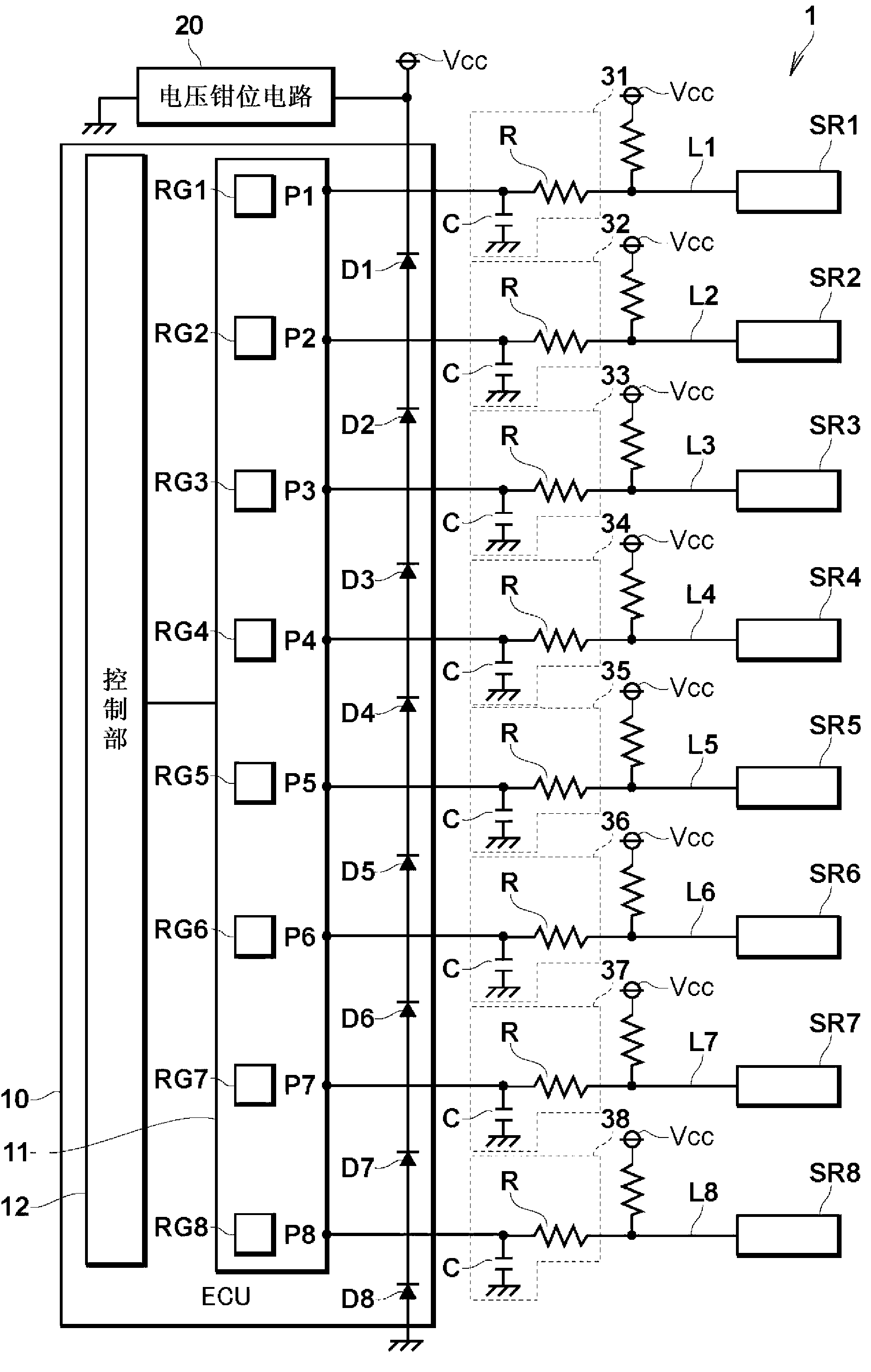
[0035] First, refer to figure 1 The overall configuration of the control device in this embodiment will be described in detail.

[0036] figure 1 It is a circuit diagram showing the structure of the control device in this embodiment.

[0037] figure 1 The control device 1 shown is typically a control device capable of controlling a fuel injection operation for a vehicle internal combustion engine (not shown). This control device 1 includes: an ECU (Electronic Control Unit: electronic control unit) 10 as a microcomputer; a voltage clamp circuit 20; L1-L8 are electrically connected between the EUC 10 and the sensors SR1-SR8 correspondingly.

[0038] Each of the sensors SR1 to SR8 is typically a sensor for detecting a physical quantity related to the control of the operating state of various electrical components that def...


PUM


Abstract

A control unit (12) causes an A / D converter (11) to perform A / D conversion for only analogue signals received from those sensors among a plurality of sensors (SR1 to SR8) required in processing to be executed by the control unit to control the operation of an electric component. The control unit (12) thereby obtains only digital signal data required in the processing, and reads out only the digital signals required in the processing.

Description

technical field [0001] The present invention relates to a control device for controlling electrical components of a vehicle, and more particularly to a control device including an analog / digital converter for converting an analog signal into a digital signal. Background technique [0002] In recent years, vehicles such as automobiles are equipped with various electrical components, and in order to control the electrical components with high precision, analog / digital converters ( Hereinafter, a control device referred to as an A / D converter) that converts analog signals from various sensors that detect physical quantities indicative of operating states of a vehicle's internal combustion engine, etc., into digital signals. [0003] In the control device, the number of electrical components to be controlled tends to increase, and it is necessary to control such a plurality of electrical components with higher precision, so the load on the A / D converter of the control device als...

Claims


Application Information

Patent Timeline
Patent Type & Authority Applications(China)
IPC IPC(8): G06F3/05H03M1/12
CPCH03M1/1225
Inventor 阿相龙治结城太一
Owner KEIHIN CORP
Learn More