Large-span non-floor type cast-in-place beam falsework and construction method thereof

A cast-in-place girder frame, non-floor type technology, applied in bridges, bridge construction, erection/assembly of bridges, etc., can solve the problems of high construction cost, waste of resources, long construction period, etc., to reduce construction cost and reduce construction cost , the effect of saving resources

Active Publication Date: 2013-08-14
中铁二十四局集团安徽工程有限公司 +1
View PDF6 Cites 21 Cited by
  • Summary
  • Abstract
  • Description
  • Claims
  • Application Information

AI Technical Summary

Problems solved by technology

[0003] The purpose of the present invention is to solve the problems of long construction period, high construction cost and waste of resources caused by the inability to use full-scale support for construction or the necessity of foundation treatment and post-strut construction in some special geological or construction environments. To achieve the purpose of minimizing foundation treatment or not performing foundation treatment during the construction of the scaffolding method, and provide a large-span non-floor cast-in-place beam scaffolding and its construction method

Method used


Image

  • Large-span non-floor type cast-in-place beam falsework and construction method thereof

Examples


Embodiment Construction

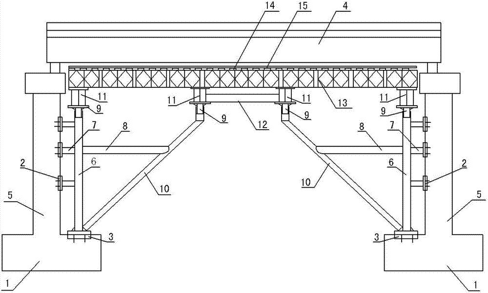
[0026] see figure 1 , the structural form of the large-span non-floor type cast-in-place girder frame in this embodiment is: the two-side supports are symmetrically arranged on the two-side caps 1 and the pier body 5 for supporting the cast-in-place beam 4, and the structure of the two-side supports The form is: on the top of the concrete cap 1, set the pre-embedded steel plate 3 through the anchor bolt; The steel pipe column 6 and the corbel slant support 10 are respectively supported on the pre-embedded steel plate 3 of the platform; the pier body column connecting steel pipe 7 at different height positions is respectively arranged between the embedded steel plate 2 of each pier body and the steel pipe column 6; A corbel horizontal support 8 is arranged between the corbel oblique supports 10; an unloading sand cylinder top cap 9 is respectively arranged on the top of the steel pipe column 6 and the corbel oblique support 10, and a double I-beam 11 is arranged on the unloadin...


PUM


Abstract

The invention discloses a large-span non-floor type cast-in-place beam falsework and a construction method thereof. The large-span non-floor type cast-in-place beam falsework is characterized in that two side supports are symmetrically arranged on two side bearing platforms and piers used for bearing a cast-in-place beam, embedded bearing platform steel plates are arranged at the top of the concrete bearing platforms via foundation bolts, embedded pier steel plates are respectively arranged at different height on side portions of the concrete piers via foundation bolts, vertical steel tube columns and bracket side stays are respectively arranged on the embedded bearing platform steel plates, and vertical pier column connecting steel tubes are arranged at different height between the embedded pier steel plates and the vertical steel tube columns, and horizontal bracket supports are arranged between the vertical steel tube columns and the bracket side stays, sand cylinder disassembling top caps are respectively arranged at the top of the vertical steel tube columns and the bracket side stays, double-spliced H-shaped steel is arranged on the sand cylinder disassembling top caps, and Bailey beams are arranged on the double-spliced H-shaped steel. The large-span non-floor type cast-in-place beam falsework is used in construction of cast-in-place continuous beams and continuous steel structures, foundation treatment can be omitted, and construction cost and safety risks in construction are reduced.

Description

technical field [0001] The invention relates to the technical field of cast-in-place frame construction in bridge engineering, in particular to a cast-in-place frame and a construction method thereof. Background technique [0002] With the development of domestic highways and railways, beam types such as cast-in-place continuous beams and cast-in-place continuous steel beams for long-span and large-width bridges are more and more widely used in engineering construction. At present, such bridges are usually constructed by the method of full support or steel pipe frame. In special areas such as crossing rivers and soft foundations, the full house support method obviously cannot meet the needs of the site. At this time, steel pipe scaffolding method construction is more common. The strength and stability of the temporary support where the fulcrum is located is the key to the entire construction process and the quality assurance of the main project. Therefore, foundation treatm...

Claims


Application Information

Patent Timeline
Patent Type & Authority Applications(China)
IPC IPC(8): E01D21/00
Inventor 韩俊鲁璐王辅圣严来章董景超乐伟
Owner 中铁二十四局集团安徽工程有限公司
Why Eureka
Try Eureka