Connection joint of concrete column and steel beam

A technology for concrete columns and connecting nodes, which is applied to buildings and building structures, can solve problems such as complex operations and difficult repairs, and achieve the effects of improving construction progress, simplifying construction difficulties, and reducing matching gaps.

Inactive Publication Date: 2013-08-14
汪洋 +1
View PDF8 Cites 14 Cited by
  • Summary
  • Abstract
  • Description
  • Claims
  • Application Information

AI Technical Summary

Problems solved by technology

For example, the patent (201020212502.8) discloses a joint between a concrete column and an I-beam, including the beam-column body, the concrete beam-column is socketed in the cement column connecting sleeve, and the steel bars in the concrete beam-column are welded to the steel bars in the cement beam-column connecting sleeve In the implanted hole, the two sides of the cement beam-column connecting sleeve are respectively connected with the I-beams on both sides by inserting bolts into the I-beam connection bolt holes. This scheme also has disadvantages such as difficult repair and complicated operation. Due to the defects in the scheme, after many tests, calculations and practical applications, a joint structure with simple construction, high strength, repairable and replaceable is proposed

Method used


Image

  • Connection joint of concrete column and steel beam
  • Connection joint of concrete column and steel beam
  • Connection joint of concrete column and steel beam

Examples


Embodiment 1

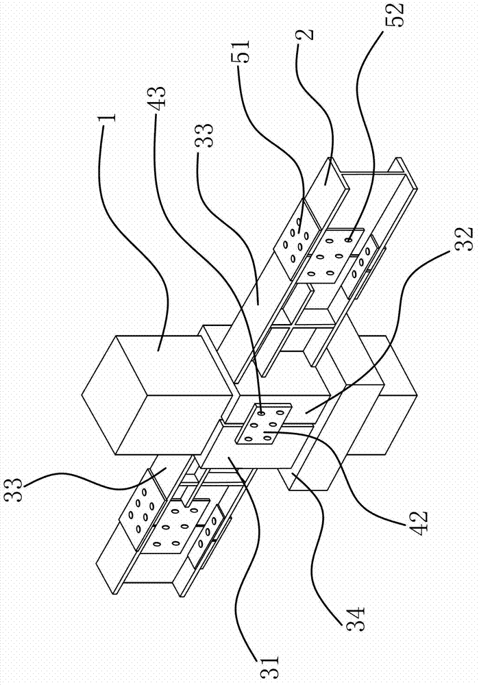
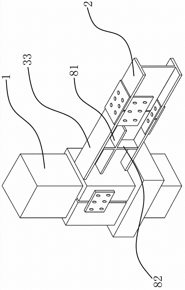
[0030] Such as figure 1 , figure 2 , image 3 with Figure 5 As shown, a connection node between a concrete column and a steel beam includes a concrete column 1 and a steel beam 2. This node includes a half-steel jacket 31 and a half-steel jacket 2 32, and the half-steel jacket 31 and the half-steel jacket 2 32 can be After the connection is disassembled and connected, it can be set on the concrete column 1; the first half-steel sleeve 31 and / or the second half-steel sleeve 32 are welded and fixedly connected with the connecting arm 33, and the first half-steel sleeve 31 and the second half-steel sleeve 32 are connected to the connecting arm 33 are fixedly connected by double-sided fillet welds, and the connecting arm 33 is detachably connected to the steel beam 2; the concrete column 1 is provided with a shoulder 34, and the first half steel sleeve 31 and the second half steel sleeve 32 can lean against the On the shoulder 34, the first half steel sleeve 31 and the second h...

Embodiment 2

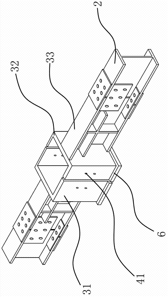
[0037] Such as Image 6 As shown, the content of the present embodiment is roughly the same as that of the first embodiment, the difference being that: the half-steel sleeve-31 is fixedly provided with several connecting plates-42, and the connecting plates-42 connect with the semi-steel through several connecting bolts-43. Set 2 32 is connected, in order to better reduce construction difficulty and improve installation accuracy, one end of connecting plate 1 42 can be welded with semi-steel sleeve 1 31, and the other end and half-steel sleeve 2 32 can be fixed with connecting bolt 1 43 Even, what is different from the previous scheme is that the through hole on the connecting plate 42 can be opened in advance, first connect one end of the connecting plate to the half steel sleeve 32 through the connecting bolt 1 43, and then connect the other end to the half steel sleeve 32. The steel sleeve is welded at 31, and its construction is easier.


PUM


Abstract

The invention provides a connection joint of a concrete column and a steel beam, belongs to the technical field of construction engineering, and solves the technical problems of low strength, construction difficulty and the like of an existing connection joint of the concrete column and the steel beam. The connection joint of the concrete column and the steel beam comprises the concrete column, the steel beam, a half steel sleeve I and a half steel sleeve II. The half steel sleeve I and the half steel sleeve II are detachably connected and can be sleeved on the concrete column after being connected; the half steel sleeve I or the half steel sleeve II is fixedly connected with a connection arm which is detachably connected with the steel beam; and the concrete column is provided with a projecting shoulder, and the half steel sleeve I and the half steel sleeve II can abut against the projecting shoulder. The connection joint of the concrete column and the steel beam has the advantage of being high in bearing capacity and simple in construction.

Description

technical field [0001] The invention belongs to the technical field of construction engineering and relates to a connection node between a concrete column and a steel beam. Background technique [0002] The current practice of connecting nodes between concrete columns and steel beams is generally: implant steel bars in concrete columns and weld the connectors, such as a new type of concrete column-steel beam composite frame structure node disclosed in the patent (200910208481.4), including steel beams , concrete columns, connecting end plates and high-strength connecting bolts. The concrete columns include square steel barrels, longitudinal steel bars and multiple pieces of stiffening steel plates. Each stiffening steel plate is welded to the square steel barrel to form a whole, and the longitudinal steel bars pass through the grid respectively. The steel beams are connected to the outer wall of the square steel barrel through the connecting end plate and high-strength conne...

Claims


Application Information

Patent Timeline
Patent Type & Authority Applications(China)
IPC IPC(8): E04B1/58
Inventor 汪洋
Owner 汪洋
Why Eureka
Try Eureka