Aerodynamic design method of subsonic adsorption type axial compressor

An axial-flow compressor, pneumatic design technology, applied in mechanical equipment, machines/engines, non-variable-capacity pumps, etc., can solve the problems of difficult suction pipeline layout, increase in blade rotation angle, and decrease in blade strength, to avoid problems such as Blade strength and suction structure design to ensure efficient flow

Active Publication Date: 2013-08-14
HARBIN INST OF TECH
View PDF5 Cites 16 Cited by
  • Summary
  • Abstract
  • Description
  • Claims
  • Application Information

AI Technical Summary

Problems solved by technology

[0005] The purpose of the present invention is to solve the problem of boundary layer separation flow in the moving blade when the blade rotation angle increases and the stage load increases,

Method used


Image

  • Aerodynamic design method of subsonic adsorption type axial compressor
  • Aerodynamic design method of subsonic adsorption type axial compressor
  • Aerodynamic design method of subsonic adsorption type axial compressor

Examples


Embodiment Construction

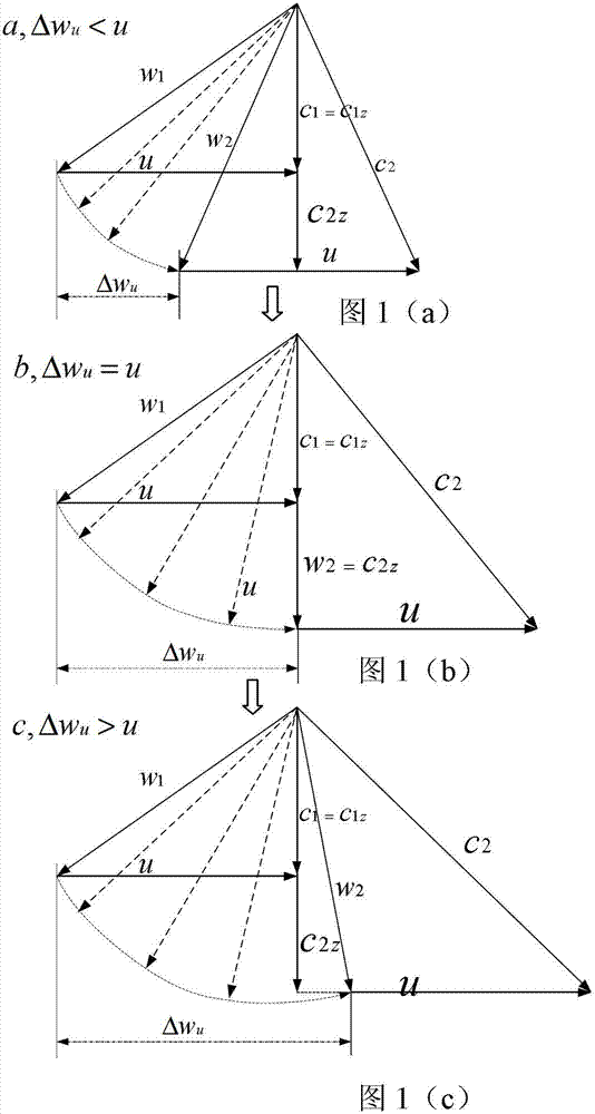
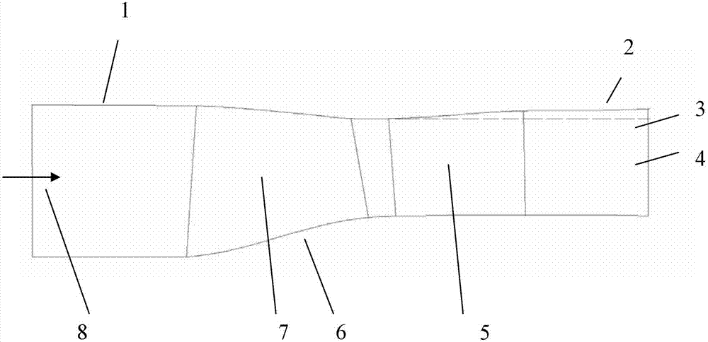
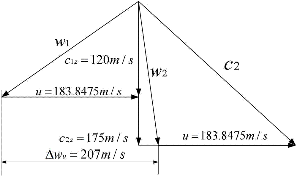
[0020] For the axial flow compressor stage with subsonic inlet relative velocity, in the conventional design, the axial velocities at the rotor blade inlet, rotor blade outlet and stator blade outlet are usually equal or have little change. On the premise that the velocity triangle at the inlet of the rotor blade remains unchanged, as the stage load increases to a certain level, boundary layer flow separation will occur inside the rotor blade. At this time, by increasing the contraction range of the meridional flow channel, the axial velocity of the rotor blade outlet is increased to reduce the reverse pressure gradient of the gas in the rotor blade, avoid boundary layer separation flow in the rotor blade, and improve the gas flow efficiency in the rotor blade. From a one-dimensional point of view, the method for determining the value of the increase in the axial velocity at the outlet is as follows:

[0021] D = 1 - ...


PUM


Abstract

The invention belongs to the technical field of axial compressors, and relates to an aerodynamic design method of a subsonic adsorption type axial compressor, in order to solve the problems of increasing of blade rotating angles of a subsonic axial compressor and boundary layer separated in a moving blade during stage load increasing as well as the problems of suction pipeline layout difficulty, blade strength reduction and the like caused by boundary layer suction in the moving blade. On the premise of unchanging an inlet velocity triangle, with design stage load coefficient increasing gradually and exceeding a conventional design value, outlet axial velocity of the moving blade is increased greatly so as to reduce diffusion factors in the moving blade, so that efficient flow of the moving blade is guaranteed; and boundary layer suction is utilized for achieving internal flow of a fixed blade. As boundary layer suction is performed in the moving blade as well as the fixed blade, problems of poor blade strength of a rotatable part and difficulty in suction structure design are solved effectively; and as compared with a tandem cascade technique, the aerodynamic design method has the advantages that blades can be decreased, and accordingly size and weight of an engine are reduced. The method can be applied to aerodynamic design of aero-engines with high thrust-weight ratio.

Description

technical field [0001] The invention relates to an aerodynamic design method of a subsonic axial flow compressor, which belongs to the technical field of axial flow compressors. Background technique [0002] The basic components of an axial flow compressor are composed of a rotor and a stator. For the compressor, its single-stage pressure ratio is increased, which can effectively reduce the size and weight of the engine and increase the thrust-to-weight ratio of the aeroengine. Generally, there are two main methods to increase the pressure ratio of the compressor stage, increasing the circumferential speed of the rotor or increasing the bending angle of the rotor blades to obtain a large torsional speed gain. When the peripheral speed remains constant, on the premise of ensuring the efficiency of the compressor stage, further increasing the twisting speed of the rotor is the only way to increase the pressure ratio of the compressor stage. [0003] In the aerodynamic design...

Claims


Application Information

Patent Timeline
IPC IPC(8): F04D29/38
Inventor 王松涛胡应交
Owner HARBIN INST OF TECH
Why Eureka
Try Eureka