Decompression chamber structure of a large flow balanced pressure regulating valve

A pressure regulating valve, balanced technology, applied in the direction of balance valve, safety valve, valve device, etc., can solve the problems affecting product quality and service life, unsuitable for low temperature environment, high requirements for bellows, to avoid easy wear and failure, The effect of low cost and few sealing links

Inactive Publication Date: 2015-12-23
铜陵市三圆机械制造有限公司
View PDF7 Cites 0 Cited by
  • Summary
  • Abstract
  • Description
  • Claims
  • Application Information

AI Technical Summary

Problems solved by technology

[0003] However, with the application of various fuel gases such as compressed natural gas (CNG) or liquids such as liquefied natural gas (LNG) in the automotive industry, traditional diaphragm pressure regulators often show many disadvantages under complex working conditions , such as the rupture and wear of the diaphragm; the inadaptability to the low temperature environment; and the vibration of large flow and strong air flow, etc., directly affect the quality and service life of the product
[0004] However, other structures on the market, such as the piston structure, mostly use multi-stage decompression, which is complicated in structure and high in cost; the bellows structure has high requirements for bellows and high cost

Method used


Image

  • Decompression chamber structure of a large flow balanced pressure regulating valve
  • Decompression chamber structure of a large flow balanced pressure regulating valve
  • Decompression chamber structure of a large flow balanced pressure regulating valve

Examples


Embodiment Construction

[0026] The specific implementation of the present invention will be described in further detail below by describing the embodiments with reference to the accompanying drawings, so as to help those skilled in the art have a more complete, accurate and in-depth understanding of the inventive concepts and technical solutions of the present invention.

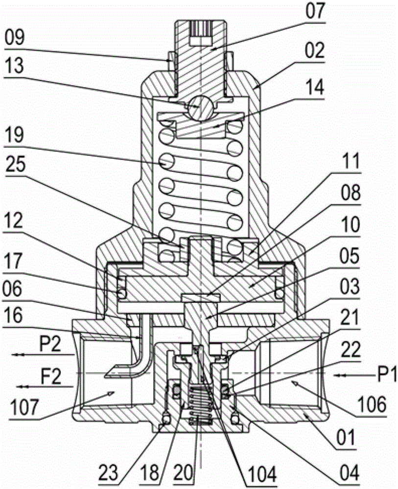
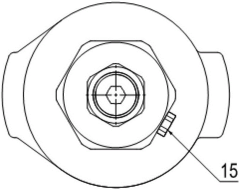
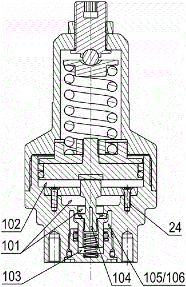
[0027] Such as Figure 1 to Figure 4 The structure of the present invention shown is a decompression chamber structure of a large-flow balanced pressure regulating valve.

[0028] In order to solve the problems existing in the prior art and overcome its defects, and realize the purpose of the invention that different flow requirements have little influence on the outlet pressure, the technical solution adopted by the present invention is:

[0029] Such as Figure 1 to Figure 4 As shown, a large-flow balanced pressure regulating valve of the present invention, the pressure regulating valve includes a valve body 01, a valve cover 02...


PUM


Abstract

The invention discloses a pressure reduction cavity structure for a high-flow balanced pressure regulating valve. The pressure regulating valve comprises a valve body, a valve cover, a valve spool, an input channel and an output channel, the pressure regulating valve is provided with a piston, one end of the piston contacts with the valve spool through a presser bar, the other end of the piston contacts with a regulating spring, a partition plate is arranged in the valve body and divides a cavity containing the output channel and a cavity containing the piston, a Venturi tube is arranged on the partition plate, and the output channel is communicated with the cavity containing the piston through the Venturi tube. By the aid of the technical scheme, the Venturi tube is arranged at an outlet of the valve, and different flow demands less affect outlet pressure. Therefore, pressure reduction and stabilization effects under different working conditions are achieved, and the pressure regulating valve is simple in structure, less in sealing link, sensitive in response, high in flow and stable in output pressure.

Description

technical field [0001] The invention belongs to the technical field of pressure regulating valves for liquid or gas. More specifically, the invention relates to a structure of a decompression cavity of a large-flow balanced pressure regulating valve. Background technique [0002] In the current domestic and foreign markets, large-flow regulators (such as flow rates greater than 100Nm3 / h) mostly use traditional diaphragm structures. For general industrial applications, due to single working conditions, simple use conditions, and low service life requirements , the membrane structure is suitable. [0003] However, with the application of various fuel gases such as compressed natural gas (CNG) or liquids such as liquefied natural gas (LNG) in the automotive industry, traditional diaphragm pressure regulators often show many disadvantages under complex working conditions , such as rupture and wear of the diaphragm; inadaptability to the low temperature environment; and vibrati...

Claims


Application Information

Patent Timeline
Patent Type & Authority Patents(China)
IPC IPC(8): F16K17/20
Inventor 李友生张凤记
Owner 铜陵市三圆机械制造有限公司
Why Eureka
Try Eureka