Microchannel Heat Exchanger Facilitating Reduced Refrigerant Charge

A micro-channel heat exchanger and micro-channel technology, applied in refrigerators, refrigeration components, refrigeration and liquefaction, etc., can solve the problems of reducing heat exchanger capacity, increasing processing difficulty, and uneven flow distribution, etc., to achieve Uniform liquid separation, easy processing, and improved heat transfer capacity

Inactive Publication Date: 2015-09-23
SHANGHAI JIAOTONG UNIV
View PDF5 Cites 2 Cited by
  • Summary
  • Abstract
  • Description
  • Claims
  • Application Information

AI Technical Summary

Problems solved by technology

When used in an air-conditioning heat pump, when the refrigerant enters the flat tube from the header, the flow distribution is uneven due to the pressure drop, thereby reducing the heat exchanger capacity of the heat exchanger. The flat tube port used in this technology shrinks to form a horn shape , the two-phase fluid entering the flat tube from the header still needs to pass through the trumpet-shaped special-shaped tube, which will lead to more serious uneven distribution of refrigerant. In addition, from the perspective of processing methods, the middle part of the flat tube in this invention is extruded , the bell mouth at both ends of the flat tube cannot be formed at one time, and the adapter and the flat tube are required to be welded, which increases the difficulty of processing

Method used


Image

  • Microchannel Heat Exchanger Facilitating Reduced Refrigerant Charge
  • Microchannel Heat Exchanger Facilitating Reduced Refrigerant Charge
  • Microchannel Heat Exchanger Facilitating Reduced Refrigerant Charge

Examples


Embodiment 1

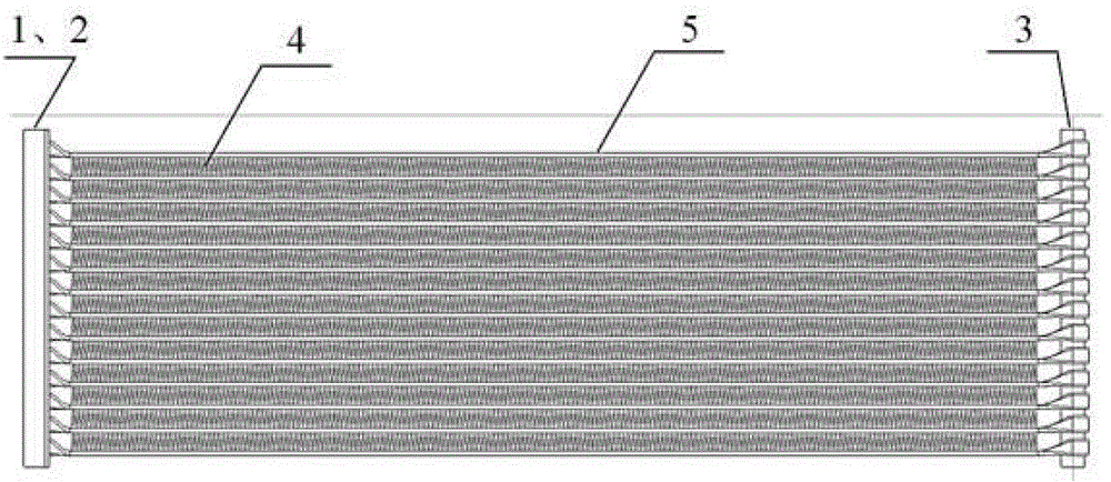
[0026] Such as figure 1 As shown, this embodiment includes: the inlet header 2 and the outlet header 1 on the same side, the fixed pipe 3 on the opposite side, and the two ends are respectively connected to the inlet header 2 and the outlet header 1 and wound around Pass through the microchannel flat tube 5 of the fixed tube 3.

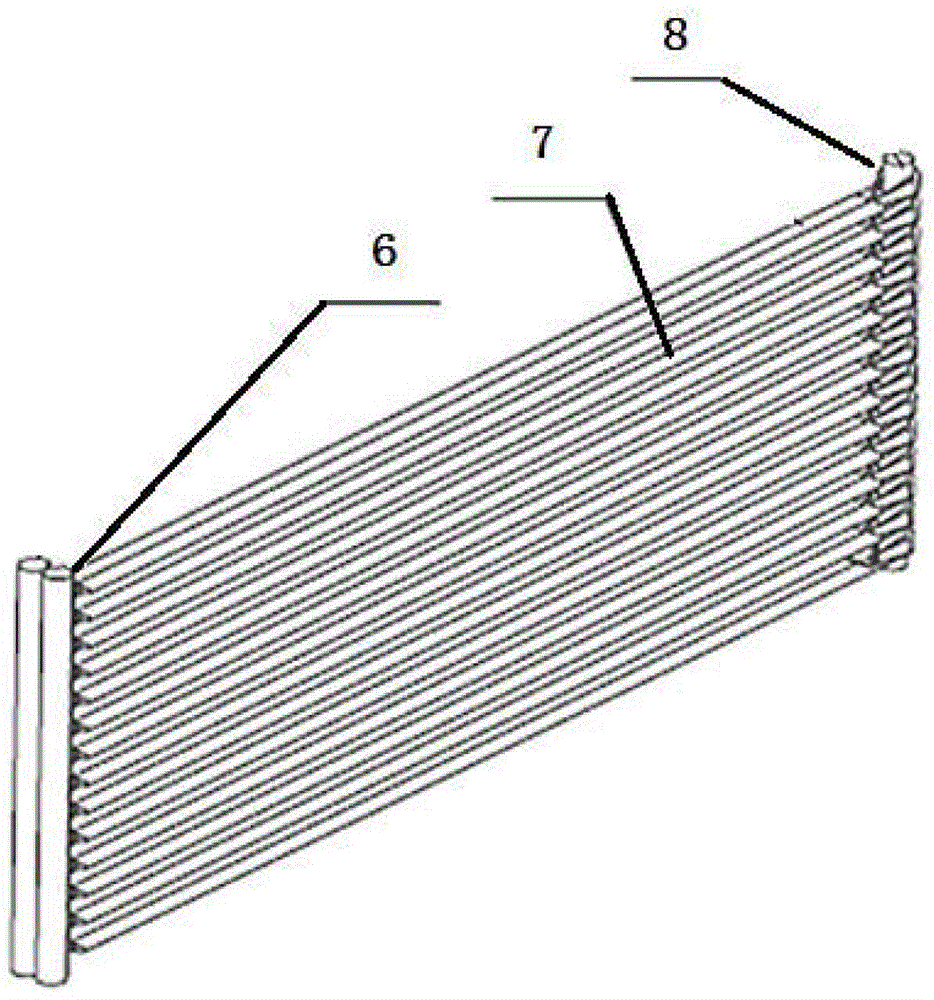
[0027] Such as figure 2 As shown, the microchannel flat tube 5 includes: a connecting part 6, a working part 7 and a transition part 8, wherein: the connecting part 6 is located at both ends of the microchannel flat tube 5 and is connected to the inlet header 2 and the outlet header respectively. The flow tubes 1 are connected, the transition part 8 is located in the middle of the microchannel flat tube 5 and is in contact with the outer surface of the fixed tube 3, the working part 7 is located between the inlet header 2, the outlet header 1 and the fixed tube 3, and the working part 7 is provided with fin 4.

[0028] Such as image 3 As shown, ...

Embodiment 2

[0037] When the inlet header 2 and the outlet header 1 are on both sides, it can be used as Figure 5 The microchannel flat tube mid-stage shown is set up in a finned manner. Then the device only includes inlet header 2 and outlet header 1 located on both sides and microchannel flat tubes 5 connected to inlet header 2 and outlet header 1 respectively.

[0038] The corresponding microchannel flat tube 5 includes: a connecting part and a working part, and fins are arranged on the whole working part.

[0039] The connecting part is a rotating transition structure.


PUM


Abstract

The invention discloses a micro-channel heat exchanger facilitating reducing refrigerant charge in the technical field of heat exchangers. The micro-channel heat exchanger comprises an inlet header and an outlet header which are located on the same side, a fixing pipe located on the opposite side, and a micro-channel flat pipe rounding the fixing pipe, wherein the two ends of the micro-channel flat pipe are connected with the inlet header and the outlet header respectively. According to the micro-channel heat exchanger, the diameters of the headers are reduced, so that the volume in the heat exchanger is reduced, and a purpose of reducing the charge of a system is achieved; the minimum inner diameters of the headers of the original heat exchanger are greater than the width of the flat pipe, and are 12-26mm generally; the minimum inner diameters of the headers can be reduced to be the same as the thickness of the flat pipe, and can be approximately 1-2mm; the refrigerant charge can be reduced further; and a standard that R290 can be normally used in a home air conditioner is reached.

Description

technical field [0001] The invention relates to a device in the technical field of heat exchangers, in particular to a micro-channel heat exchanger which is beneficial to reduce refrigerant charge. Background technique [0002] At present, the commonly used refrigerant in household air conditioners is R22, which has a lower ODP. The HPMP goal of the room air conditioner industry is to gradually replace HCFC-22 through three stages: the first stage is to realize the consumption of R22 in 2013 The amount is frozen at the baseline level of 74,545 tons; the second stage is to achieve a 10% reduction from the baseline level in 2015; the third stage is to reduce by 97.5% in 2030. Considering that ODP is zero and the GWP value is low, R290 can be used to replace R22, but R290 is extremely flammable. According to European and American standards, if flammable R290 is used in household air conditioners, its dosage should be controlled at 150g For a moment, the current refrigeration s...

Claims


Application Information

Patent Timeline
Patent Type & Authority Patents(China)
IPC IPC(8): F25B39/00
Inventor 陈江平徐博严瑞东黄嘉乐
Owner SHANGHAI JIAOTONG UNIV
Why Eureka
Try Eureka