Method capable of displaying real-time electric quantity state and electronic scale

A technology of real-time power and electronic scales, which is applied in the direction of weighing indicating devices and single semiconductor device testing, etc. It can solve the problems of no power, can not display the remaining battery power, no power display, etc., and achieve the effect of high brightness

Inactive Publication Date: 2013-08-14
倪俊
View PDF7 Cites 0 Cited by
  • Summary
  • Abstract
  • Description
  • Claims
  • Application Information

AI Technical Summary

Problems solved by technology

[0004] Existing electronic scales usually use batteries as a power source, but because there is no power display function, the remaining battery power cannot be displayed during normal use, so it is easy to suddenly run out of power and affect the user's use. At this time, if it is in an outdoor environment, For example, in non-indoor business places such as vegetable markets and roadsides, it will cause great inconvenience.

Method used


Image

  • Method capable of displaying real-time electric quantity state and electronic scale
  • Method capable of displaying real-time electric quantity state and electronic scale
  • Method capable of displaying real-time electric quantity state and electronic scale

Examples


Embodiment Construction

[0028] In order to further understand the technical features and content of the present invention, the following detailed description will be given in conjunction with the accompanying drawings.

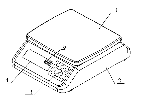
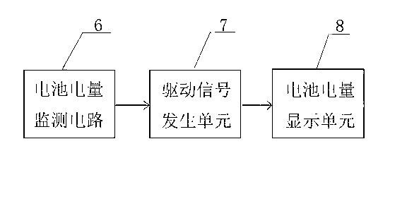
[0029] figure 1 It is a structural front view of an electronic scale capable of displaying real-time power status in the present invention; figure 2 It is a structural block diagram of the battery power monitoring process in the present invention.

[0030] like figure 1 , figure 2 As shown, an electronic scale capable of displaying real-time power status, including an electronic scale tray 1, an electronic scale housing 2, an electronic scale button 3 and a rechargeable battery (not shown in the figure), is characterized in that: In the main body, a power display unit 5 is set, and the power display unit 5 is set on the liquid crystal display 4 of the electronic scale.

[0031] In addition, the above-mentioned electronic scale body also includes a battery power monitoring circu...


PUM


Abstract

The invention relates to a method capable of displaying a real-time electric quantity state and an electronic scale. The electronic scale comprises an electronic scale body and a rechargeable battery. The electronic scale is characterized in that a battery electric quantity monitoring circuit, a driving signal generation unit and a battery electric quantity display unit are arranged in the electronic scale body, the battery electric quantity monitoring circuit is used for monitoring the electric quantity state of the rechargeable battery, and the electric quantity state is displayed through the battery electric quantity display unit; the rechargeable battery is electrically connected to the battery electric quantity monitoring circuit, and the battery electric quantity monitoring circuit is connected with the battery electric quantity display unit after the battery electric quantity monitoring circuit passes through the driving signal generation unit; and the battery electric quantity monitoring circuit consists of a battery electric quantity monitoring unit, a single-chip microcomputer and an electric quantity prompting module. By adopting the method and the electronic scale, when a user uses the electronic scale, the battery state information can be accurately known; and when the electric quantity of the battery is low, a prompt can be automatically given out to prompt the user to charge in time, the situations that the power of the electronic scale is suddenly cut off when the electronic scale is in use and the use is influenced are effectively avoided, and long-term stable use is realized.

Description

technical field [0001] The invention relates to the technical field of power management in electronic scales, in particular to an electronic scale capable of displaying battery power status. Background technique [0002] As a commonly used measurement and weighing tool nowadays, electronic scales measure and display the mass of objects by using electronic technology. They have the characteristics of high precision and fast weighing. , SCM circuit, display circuit, keyboard circuit, communication interface circuit, regulated power supply circuit and other circuits. [0003] At present, electronic scales also use sensor technology, electronic technology and computer technology to meet the requirements of fast, accurate, continuous and automatic weighing in real life, and effectively eliminate human errors at the same time, making it more in line with legal measurement management and industrial standards. Application requirements for production process control. Compared with ...

Claims


Application Information

Patent Timeline
Patent Type & Authority Applications(China)
IPC IPC(8): G01R31/26G01G23/18
Inventor 倪俊
Owner 倪俊
Why Eureka
Try Eureka