Longitudinal differential protection current phase compensation method for YNd7 transformer

A technology of current phase compensation and differential protection, applied in the direction of emergency protection circuit devices, electrical components, etc., can solve the problems of not being able to adapt to wiring groups and wiring combinations, etc., and achieve the effect of small changes in the secondary circuit and easy implementation

Inactive Publication Date: 2013-08-14
STATE GRID CORP OF CHINA +2
View PDF3 Cites 16 Cited by
  • Summary
  • Abstract
  • Description
  • Claims
  • Application Information

AI Technical Summary

Problems solved by technology

However, at present, the differential protection current software phase compensation method of various transformer protection manufacturers can only adapt to the transformer wirin

Method used


Image

  • Longitudinal differential protection current phase compensation method for YNd7 transformer
  • Longitudinal differential protection current phase compensation method for YNd7 transformer
  • Longitudinal differential protection current phase compensation method for YNd7 transformer

Examples


Embodiment Construction

[0020] specific implementation plan

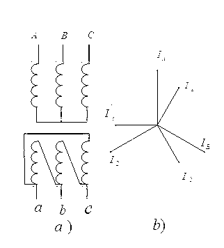
[0021] 1. Current phase relationship on both sides of YNd1 transformer

[0022] Such as figure 1 It is the wiring diagram of YNd1 transformer and the current vector diagram on both sides, a) is the wiring diagram of YNd1 transformer, and b) is the current vector diagram of YNd1 transformer. Depend on figure 1 b) It can be seen that the Y-side current phase is 30 degrees ahead of the D-side current phase.

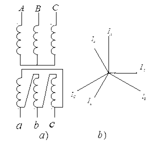
[0023] 2. Current phase relationship on both sides of YNd7 transformer

[0024] Such as figure 2 It is the wiring diagram of the YNd7 transformer and the current vector diagram on both sides, a) YNd7 is the transformer wiring diagram, b) is the current vector diagram on both sides of the YNd7 transformer. Depend on figure 2 b) It can be seen that the Y-side current phase lags behind the d-side current phase by 150 degrees.

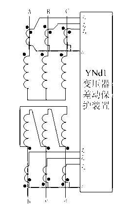
[0025] 3. The current phase relationship between YNd7 and YNd1 transformer d side

[0026] Because the ...


PUM


Abstract

The invention belongs to a relay protection controlling technology of power transmission and distribution network, and relates to a longitudinal differential protection current phase compensation method for an YNd7 transformer, which comprises the steps of enabling TA secondary windings of the high-voltage side and the low-voltage side of the YNd7 transformer to be in Y connection; b, connecting the A-phase current, B-phase current and the C-phase current of the Y-side TA secondary windings of the transformer to loops of the A-phase current, the B-phase current and the C-phase current of a YNd11 transformer differential protection device; connecting each phase current of the d-side TA secondary windings of the transformer into the YNd1 transformer differential protection device according to the reversed polarity of each d-side phase current of the YNd7 transformer; and d, utilizing the YNd1 transformer protection device to finally realize the differential protection phase compensation of the YNd7 transformer. The longitudinal differential protection current phase compensation method for the YNd7 transformer is simple in principle, convenient to implement and can adapt to the longitudinal differential protection current phase compensation of the YNd7 connecting transformer.

Description

technical field [0001] The invention belongs to the relay protection control technology of electric power transmission and distribution network, and relates to a method for current phase compensation of longitudinal differential protection of YNd7 series transformers. Background technique [0002] Since the currents on each side of the transformer in the transmission and distribution network may have inconsistent phases, the transformer longitudinal differential protection (hereinafter referred to as the transformer differential protection) needs to perform current phase compensation. There are two methods of current phase compensation for transformer differential protection: 1. Traditional hardware phase shifting: for example, the secondary winding of Y-side current transformer (hereinafter referred to as TA) of YNd11 transformer adopts delta d-11 connection, and the secondary winding of d-side TA Use star Y-12 wiring; 2. Software phase shift: use software program and calcu...

Claims


Application Information

Patent Timeline
IPC IPC(8): H02H7/045
Inventor 汤大海易新马海薇祁明
Owner STATE GRID CORP OF CHINA
Why Eureka
Try Eureka