8*8 optical switching array oriented to fat tree topological structure

A topology, optical switching technology, applied in data switching networks, data switching through path configuration, star/tree networks, etc. The effect of reducing the number of rings

Inactive Publication Date: 2013-08-14
NAT UNIV OF DEFENSE TECH
View PDF4 Cites 8 Cited by
  • Summary
  • Abstract
  • Description
  • Claims
  • Application Information

AI Technical Summary

Problems solved by technology

At present, the main problems faced in the on-chip optical interconnection network based on the fat tree topology are how to reduce the number of microrings used in the optical switching array and how to increase the port scale of the optical switching array. The former is related to the occupation of the on-chip optical interconnection network. Chip area, power consumption, optical loss and complexity, the latter is related to the network diameter of the on-chip optical network, which in turn affects the end-to-end delay of the network
[0005] At present, the structure that can be used to construct an N×N optical switching array is mainly an optical Crossbar, also known as an optical crossbar switch matrix or a crossbar switch matrix. Its advantage is that there are independent transmission channels between all pairs of input and output ports. Therefore, this structure takes up more resources, and an N×N optical Crossbar needs to use N 2 microring

Method used


Image

  • 8*8 optical switching array oriented to fat tree topological structure
  • 8*8 optical switching array oriented to fat tree topological structure
  • 8*8 optical switching array oriented to fat tree topological structure

Examples


Embodiment Construction

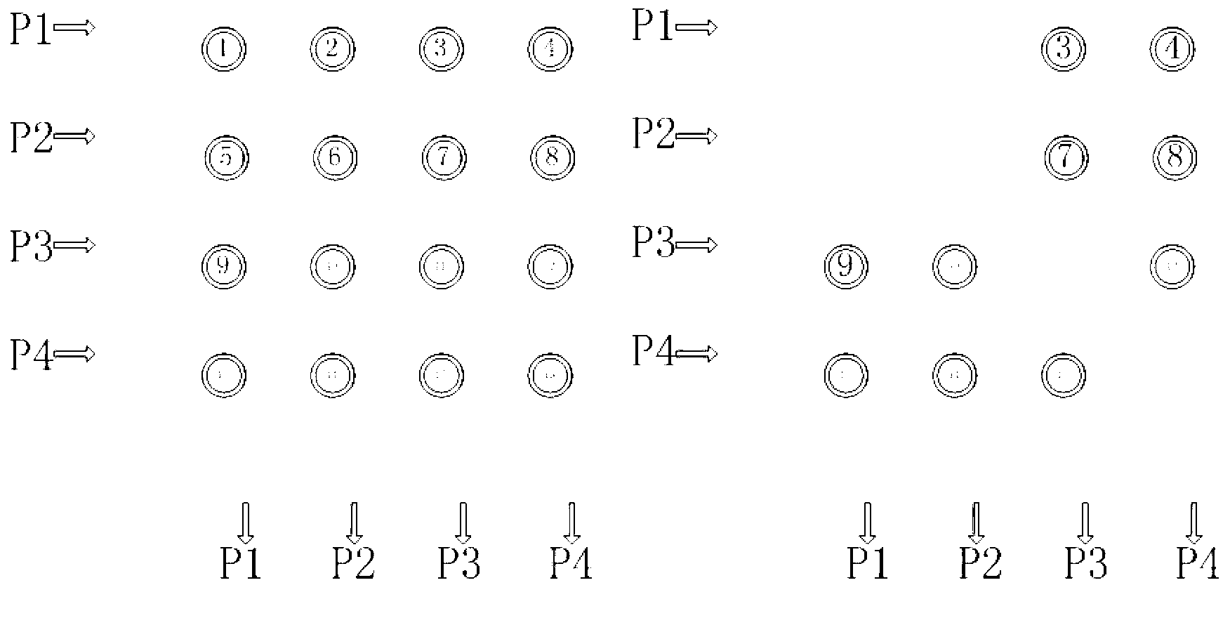
[0017] figure 1 (a) is a schematic diagram of a 4×4 optical crossbar, which consists of intersecting waveguides and microrings placed at the intersections. The optical Crossbar can provide multiple optical paths at the same time by configuring the working state of the intersection point between the input and output. The advantage of the Crossbar switching network is that there are independent switching channels between all inputs and outputs. The disadvantage is that the scalability is poor, and the number of microrings is proportional to the square of the number of ports. There are 16 microrings in this figure.

[0018] figure 1 (b) is a schematic diagram of a simplified 4×4 optical crossbar. In the figure, P1 and P3 are used as uplink ports of the fat tree, and P2 and P4 are used as downlink ports of the fat tree. The entire structure uses 10 microrings in total. Compared with the 4×4 optical Crossbar, a total of 6 micro-rings (10 more) were cut out, which are the 1st, 6th...


PUM


Abstract

The invention discloses an 8*8 optical switching array oriented to a fat tree topological structure, aiming at providing the 8*8 optical switching array for on-chip optical router oriented to the fat tree topological structure to enable the quantity of used micro-rings to be smaller and optical loss to be smaller. The 8*8 optical switching array consists of switching sub-arrays at three levels. The switching sub-arrays are connected through optical waveguides. The switching sub-array at a first level consists of four PSE1. The switching sub-array at a second level consists of four PSE1 consists of four PSE1 and eight PSE2. The switching sub-array at a third level consists of four PSE2. The optical switching sub-array at the first level realizes optical switching between ports P1, P2, P3 and P4 and the optical switching sub-array at the second level. The optical switching sub-array at the third level realizes the optical switching between ports P5, P6, P7 and P8 and the optical switching sub-array at the second level. The optical switching sub-array at the second level realizes the optical switching sub-array at the first level and the optical switching sub-array at the third level. The 8*8 optical switching array oriented to the fat tree topological structure has the advantages that the quantity of the micro-rings is smaller and the optical loss is smaller.

Description

technical field [0001] The invention relates to an optical switching array structure in the field of silicon-based optoelectronics, which can be used to build an optical router facing a fat tree topology. Background technique [0002] With the continuous improvement of the inter-core communication requirements of high-performance microprocessors, traditional on-chip networks based on electrical interconnection have been difficult to meet the strict requirements of high-performance multi-core microprocessors on the delay, bandwidth and power consumption of on-chip networks. As a new type of interconnection technology, optical interconnection can alleviate or even eliminate the delay, bandwidth and power consumption problems faced by traditional electrical interconnection, and it has opened up a new way for the design of future high-performance microprocessor network on chip. [0003] The on-chip optical interconnection network is formed by connecting transmission links, gatew...

Claims


Application Information

Patent Timeline
Patent Type & Authority Applications(China)
IPC IPC(8): H04L12/771H04L12/44H04B10/27H04L45/60
Inventor 窦文华李宝亮冯权友韩岗王俊辉鲁佳周乐文彭超任双印何磊孙家辉苏醒任斌郭龙飞叶进覃晨
Owner NAT UNIV OF DEFENSE TECH
Why Eureka
Try Eureka