Antenna isolator
A technology of antenna isolation and core wire, which is applied in the direction of TV, cable transmission adaptation, color TV parts, etc., can solve the problems of low mass production efficiency, poor product consistency, unfavorable TV sets, etc., and achieve high mass production efficiency , low cost, good shielding effect
- Summary
- Abstract
- Description
- Claims
- Application Information
AI Technical Summary
Problems solved by technology
Method used
Image

Examples
Embodiment 1
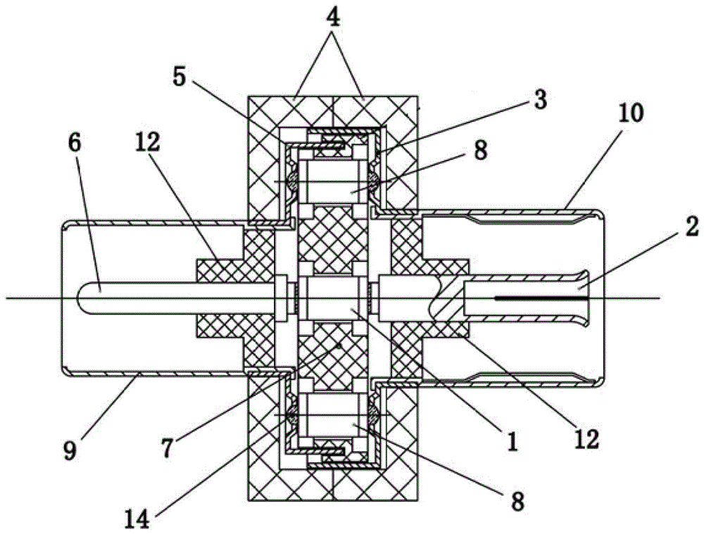
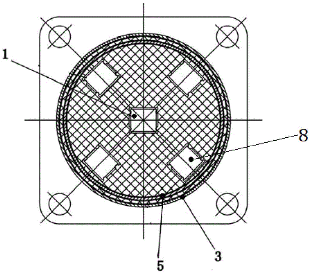
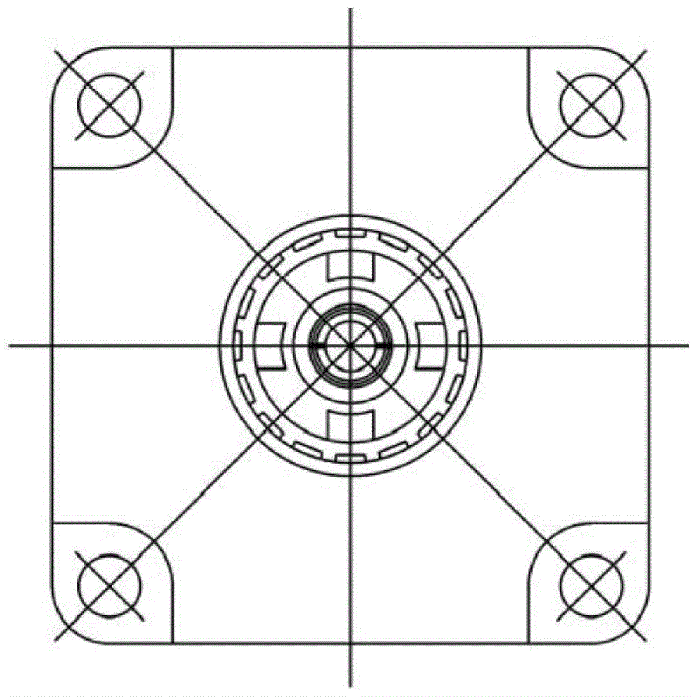
[0032] Such as Figures 1 to 3 , the antenna isolator of the present embodiment is I type, and it comprises: the large and small shielding case that opening end is oppositely arranged, and the opening end of small shielding case 5 stretches in the opening of described large shielding case 3; Large and small shielding case The outside of the shielding layer joint 9 and the second shielding layer joint 10 are respectively provided, and the first core wire joint 6 and the second core wire joint 2 distributed by the coaxial line are fixed inside the first and second shielding layer joints, There are a plurality of ground line blocking capacitors 8 and a signal DC blocking capacitor 1 inside the large and small shielding covers; a plurality of through holes are symmetrically arranged on the large and small shielding covers. Each through hole is located in the center of the corresponding pit.
[0033] The ground wire DC blocking capacitor 8 and the signal DC blocking capacitor 1 ar...
Embodiment 2
[0038] The production method of the type I antenna isolator of above-mentioned embodiment 1, it comprises the steps:
[0039] A. Set solder paste on the two electrodes of each capacitor or on the mounting holes of the large and small shields, or on multiple sets of relative through holes on the large and small shields;
[0040] B. The first and second core wire joints are respectively fixed in the first and second shielding layer joints through the insulating block 12, and at the same time, the inner ends of the first and second shielding layer joints are respectively fixed and fitted in the large , In the installation hole of the small shield;
[0041] C. The large and small shields are horizontally arranged relatively, and the DC blocking capacitors of the local lines are respectively arranged between multiple sets of relative through holes on the large and small shields, and the signal DC blocking capacitors are set Between the inner ends of the first and second shield joi...
Embodiment 3
[0045]Based on the antenna isolator of Embodiment 1 or 2 above, such as Figure 4-7 , the antenna isolator of this embodiment is L-shaped, that is, the first and second core wire connectors are vertically distributed, and the inner ends of the first and second core wire connectors are respectively connected to the two poles of the signal DC blocking capacitor through metal wires using backflow Welding.
PUM
 Abstract
Description
Claims
Application Information
 - R&D
- Intellectual Property
- Life Sciences
- Materials
- Tech Scout
- Unparalleled Data Quality
- Higher Quality Content
- 60% Fewer Hallucinations
Browse by: Latest US Patents, China's latest patents, Technical Efficacy Thesaurus, Application Domain, Technology Topic, Popular Technical Reports.
© 2025 PatSnap. All rights reserved.Legal|Privacy policy|Modern Slavery Act Transparency Statement|Sitemap|About US| Contact US: help@patsnap.com