Auto-injector

An auto-injector, trigger technology, applied in auto-injectors, syringes, hypodermic instruments, etc., can solve problems such as button inconvenience, button/plunger extension, hand tremor/jitter, etc., to achieve low parts count, The effect of reducing manufacturing costs

Active Publication Date: 2013-08-14
SANOFI AVENTIS DEUT GMBH
View PDF7 Cites 20 Cited by
  • Summary
  • Abstract
  • Description
  • Claims
  • Application Information

AI Technical Summary

Problems solved by technology

The injection force may be too high for the user, especially if the user is elderly or has dexterity issues
[0005] Button / plunger may be stretched too far
It may then be inconvenient for the user to reach the fully extended button
The combination of injection force and button extension may cause trembling / shaking of the hand which in turn increases discomfort as the inserted needle moves

Method used


Image

  • Auto-injector
  • Auto-injector
  • Auto-injector

Examples


Embodiment Construction

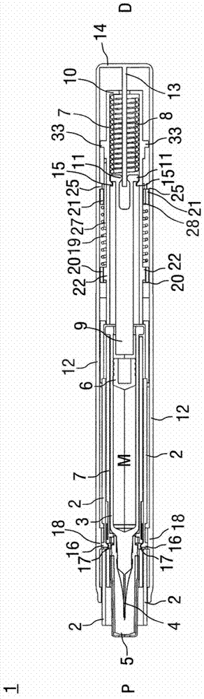
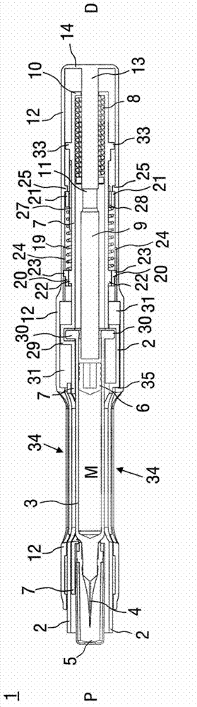
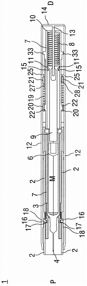
[0057] FIG. 1 shows two longitudinal sections of an autoinjector 1 in different sections rotated by approximately 90 degrees relative to each other, wherein the autoinjector 1 is in an initial state before starting an injection. The autoinjector 1 includes a chassis 2 . In the proximal part of the autoinjector 1 is arranged a barrel 3 with a hollow injection needle 4 , for example a Hypak barrel. A protective needle shield 5 is attached to the needle 4 when the autoinjector 1 or barrel 3 is assembled. A bung 6 is provided for sealing the barrel 3 distally and for moving liquid medicament M through the hollow needle 4 . The barrel 3 is held in a tubular holder 7 and is supported therein at its proximal end. The bracket 7 is slidably arranged in the chassis 2 .

[0058] A drive spring 8 in the shape of a compression spring is arranged in the distal part of the bracket 7 . The plunger 9 is used to feed forward the force of the drive spring 8 to the bung 6 .

[0059] The driv...


PUM


Abstract

The invention refers to an auto-injector (1) and to a method for operating it, the auto-injector comprising: a tubular chassis (2), a carrier subassembly comprising a tubular carrier (7) slidably arranged in the chassis (2), the carrier (7) containing a syringe (3) with a hollow injection needle (4), a drive spring (8) and a plunger (9) for forwarding load of the drive spring (8) to a stopper (6) of the syringe (3), a wrap-over trigger sleeve (12) arranged over the distal end (D) of the auto- injector (1), the trigger sleeve (12) extending at least almost over the whole length of the auto-injector (1), a control spring (19) arranged around the carrier (7), first interlock means (20, 22, 23, 24) for coupling a proximal end of the control spring (19) to either the carrier (7) for advancing it for needle insertion or to the chassis (2) for needle retraction, second interlock means (11, 13, 15) arranged for releasing the drive spring (8) for injection, third interlock means (16, 17, 18) arranged for coupling the chassis (2) to the carrier (7) for joint axial translation relative to the trigger sleeve (12), fourth interlock means (21, 25, 26, 28) arranged for coupling a distal end of the control spring (19) to either the carrier (7) for needle retraction or to the trigger sleeve (12) otherwise.

Description

technical field [0001] The invention relates to an autoinjector for delivering doses of a fluid medicament according to the preamble of claim 1 , and a method for operating an autoinjector. Background technique [0002] Administering an injection is a process that presents several risks and challenges, both psychological and physical, to the user and healthcare practitioner. [0003] Injection devices (ie, devices capable of delivering medicament from a medicament container) generally fall into two categories - manual devices and auto-injectors. [0004] In manual devices, the user must provide mechanical energy to drive fluid through the needle. This is usually done with some form of button / plunger which is continuously depressed by the user during the injection. There are various disadvantages for the user from this method. If the user stops pressing the button / plunger, the injection will also stop. This means that if the device is not being used properly (ie the plung...

Claims


Application Information

Patent Timeline
Patent Type & Authority Applications(China)
IPC IPC(8): A61M5/20
CPCA61M5/326A61M5/2033A61M5/3202A61M2005/206A61M5/3232A61M2005/2013A61M5/20
Inventor T.M.肯普M.埃克曼
Owner SANOFI AVENTIS DEUT GMBH
Why Eureka
Try Eureka