Multifunctional centralizing and oil increasing device
What is Al technical title?
Al technical title is built by PatSnap Al team. It summarizes the technical point description of the patent document.
A multi-functional centralizer technology, applied in the field of elastic fluid pumping devices, centralizers, wax scrapers and oil boosters, can solve the problems of limited oil boost effect, single function of centralizer and oil booster, etc., to achieve The effect of prolonging the inspection period of the pump, reducing the fuel consumption of hot washing, and anti-aging chemical performance
Inactive Publication Date: 2013-08-21
TIANJIN ZHENGFANG TECH DEV
View PDF10 Cites 5 Cited by
Summary
Abstract
Description
Claims
Application Information
AI Technical Summary
This helps you quickly interpret patents by identifying the three key elements:
Problems solved by technology
Method used
Benefits of technology
Problems solved by technology
[0007] In order to overcome the shortcomings of existing centralizers and oil boosters with relatively single functions and limited oil boost effects, the present invention forms a rotary centralizer and matching stop that can be turned into a plunger by changing the materials and structures of the centralizers and oil boosters. The multi-functional righting and oil increasing device characterized by the return valve integrates the functions of righting, anti-wear, anti-stripping, wax prevention, sand prevention, anti-seizing, energy saving and oil increasing, and achieves the purpose of multi-function and common oil increasing
Method used
Image
Click on the blue label to locate the original text in one second.
Reading with bidirectional positioning of images and text.
Examples
Embodiment Construction
[0028] The structure and function of the device of the present invention will be further described below through examples and in conjunction with the accompanying drawings.
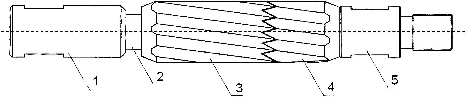
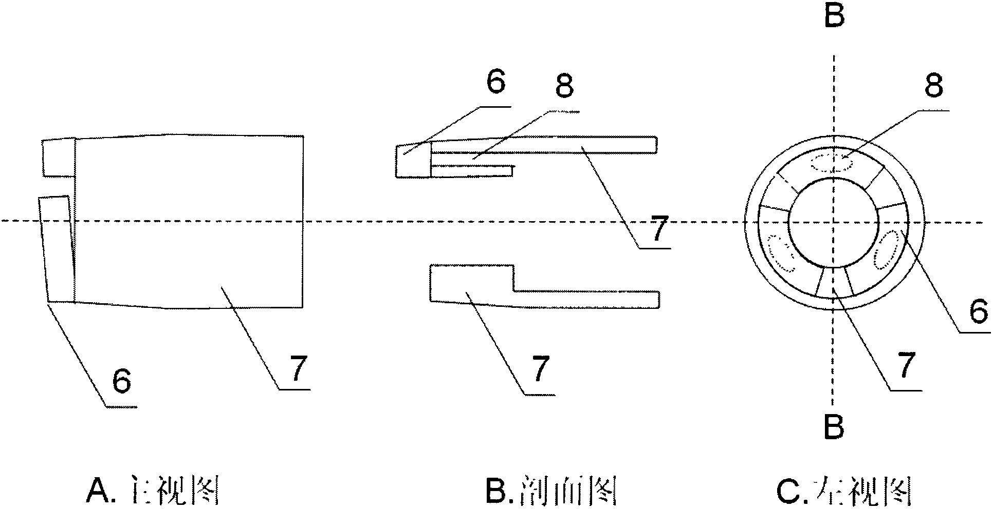
[0029] In the well, connect the movable collar (1) of the rotary centralizer to the sucker rod, and connect the fixed collar (5) to the sucker rod; install the check valve on a sucker rod adjacent to the rotary centralizer. The installation density is determined according to the specific situation and different needs. When the main purpose is to increase oil production, a set is about 100 meters; , to ensure that the adjacent rotating centralizers move with the stroke of the well section can be connected, and there is no check valve. The check valve is pushed to the lower limit by the sucker rod collar when the multi-functional righting booster device goes down the well, and is automatically semi-fixed on the tubing due to the interference fit with the tubing. When the sucker rod moves downward, the cove...
PUM
Abstract
A multifunctional centralizing and oil increasing device characterized by a rotary centralizer capable of being changed to a plunger and a matched check valve comprises a moving coupling, a rod, a floating nylon spiral guide sleeve, a fixed nylon spiral guide sleeve, a fixed coupling and a check valve. The moving coupling, the rod, the floating nylon spiral guide sleeve, the fixed nylon spiral guide sleeve and the fixed coupling are combined together to be installed between two sucker rods to form the rotary centralizer. In up moving, the floating nylon spiral guide sleeve and the fixed nylon spiral guide sleeve are meshed to have the effect of the plunger, the check valve is arranged on the close sucker rod disposed on the lower side and is semi-fixed on an oil pipe to have the effect of a fixed valve, and accordingly a set of integral oil-well pump is formed. By changing materials and structures, the multifunctional centralizing and oil increasing device integrates multiple functions such as centralizing, abrasion resisting, falling preventing, paraffin preventing, sand preventing, clamping preventing, energy saving and oil increasing, achieves the purpose of oil increasing in aspects of thermal washing oil consumption reducing, production time efficiency increasing, multi-stage pump oil extracting and pump efficiency improving, and can be widely applied to oil extracting of sucker-rod pumps of vertical shafts, directional wells, conventional heavy oil wells and common sand production wells.
Description
technical field [0001] The invention relates to a rod pump oil extraction of the oil extraction machinery technology in the petroleum industry, especially a centralizer, a wax scraper and an oil booster used on a sucker rod for preventing wax, sand, partial wear, breaking off and increasing oil. The technical field is F04C 23 / 00, specially applicable to the combination of two or more pumps for elastic fluids, each of the rotary piston or oscillating piston pump type; specially suitable for pumping devices for elastic fluids; specially suitable for Multistage pumps for elastic fluids. Background technique [0002] Oil wells, especially directional wells with rod pumps, generally face problems such as eccentric wear, wax deposition, sand production, pump jamming, breakage, etc., which affect the working rate and gas slippage, and oil-water separation affects the efficiency of pumping pumps. There are many types of centralizers and oil boosters, but their functions are relativ...
Claims
Application Information
Patent Timeline
Application Date:The date an application was filed.
Publication Date:The date a patent or application was officially published.
First Publication Date:The earliest publication date of a patent with the same application number.
Issue Date:Publication date of the patent grant document.
PCT Entry Date:The Entry date of PCT National Phase.
Estimated Expiry Date:The statutory expiry date of a patent right according to the Patent Law, and it is the longest term of protection that the patent right can achieve without the termination of the patent right due to other reasons(Term extension factor has been taken into account ).
Invalid Date:Actual expiry date is based on effective date or publication date of legal transaction data of invalid patent.