Ultrasonic sensor device

A sensor device, ultrasonic technology, applied in the field of sensors, can solve problems such as increased manufacturing costs, signal attenuation, and difficulty in welding

Inactive Publication Date: 2013-08-21
TUNG THIH ELECTRONICS
View PDF7 Cites 7 Cited by
  • Summary
  • Abstract
  • Description
  • Claims
  • Application Information

AI Technical Summary

Problems solved by technology

[0003] However, when the second lead 37 is welded to the hollow casing 31, since the hollow casing is made of aluminum, the solder joints are high and difficult to weld.
In addition, the piezoelectric film 32 needs to be electrically connected to the circuit board 11 through the adapter circuit board 33, which not only increases the material cost, but also easily causes signal attenuation. , the wires 34, 35 also need to be soldered to the adapter circuit board 33 and the circuit board 11 respectively, thus increasing the man-hours and complexity of the manufacturing process, and relatively increasing the manufacturing cost

Method used


Image

  • Ultrasonic sensor device
  • Ultrasonic sensor device
  • Ultrasonic sensor device

Examples


Embodiment Construction

[0022] Below in conjunction with accompanying drawing and embodiment the present invention is described in detail:

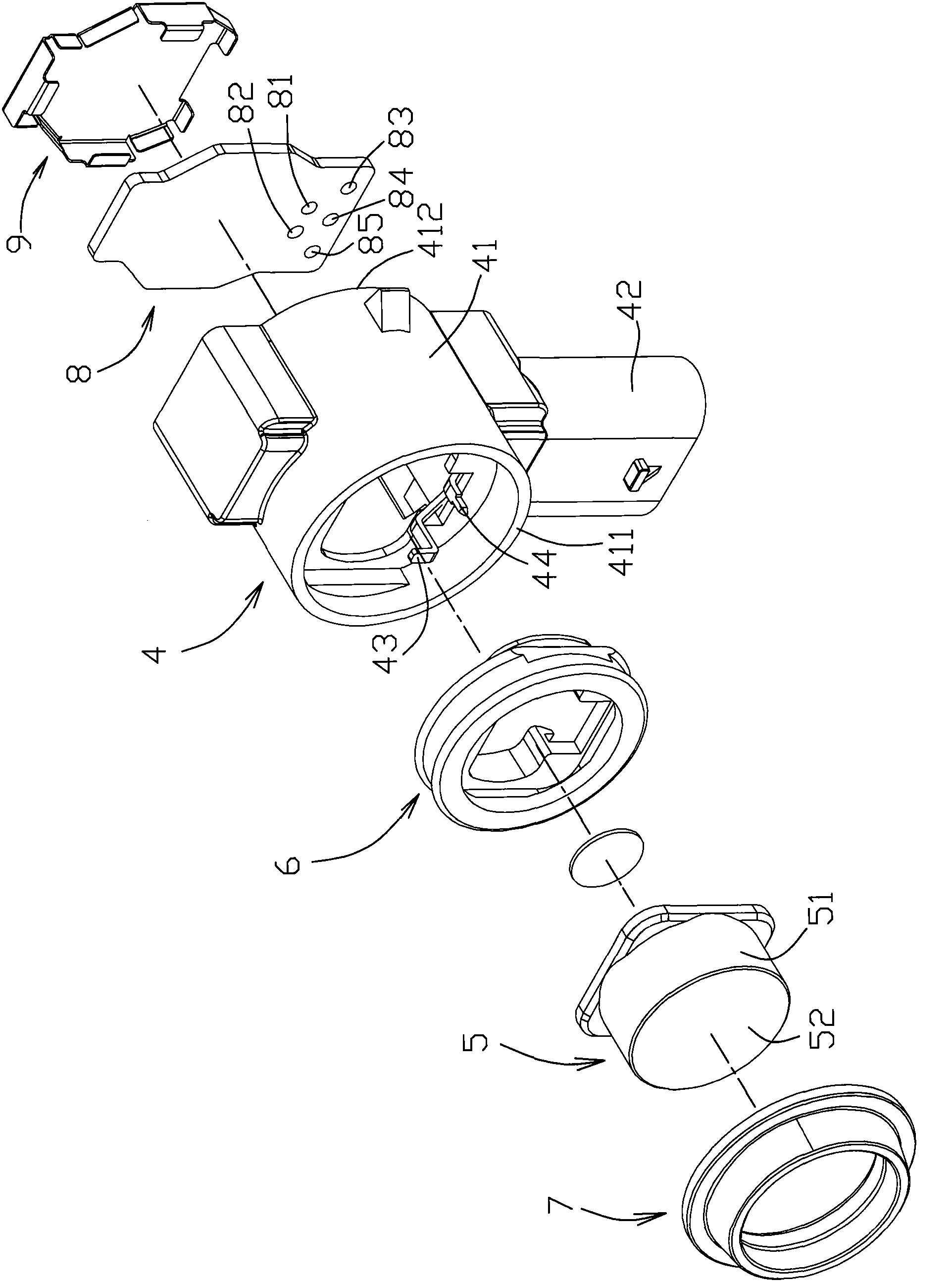
[0023] see Figure 3 to Figure 5 As shown, a preferred embodiment of the ultrasonic sensor device of the present invention includes a housing 4 , a transducer (transducer) 5 , an annular seat 6 , an O-ring 7 , a circuit board 8 and an isolation cover 9 .

[0024] The shell 4 includes a hollow shell 41, a connecting pipe portion 42 and five connecting pins 43-47. The hollow shell 41 is formed by an annular surrounding wall 48 and has a first opening which is opposite and communicated with each other. 411 and a second opening 412 . One end of the connecting pipe portion 42 is connected to the surrounding wall 48 of the hollow shell 41, and the other end has a third opening 421, and in this embodiment, the connecting pipe portion 42 and the hollow shell 41 are integrally formed, but This is not the limit. These pins 43-47 are fixed in the hollow housing 41, one ...


PUM


Abstract

The utility model discloses an ultrasonic sensor device, which comprises a hollow shell, a connecting tube part connected with the hollow shell, five pins, a sensor and a circuit board, wherein one end of each pin is positioned at a first opening of the hollow shell, the other ends of two pins are positioned at a second opening of the hollow shell, and the other end of the other three pins are extended into the connecting tube part and positioned at a third opening of the connecting tube part; the sensor is provided with an opening, and the side wall of the sensor is provided with a ground wire hole; the sensor is fixed at the second opening of the hollow shell, so that the other end of one of the pins extended to the second opening extends into the opening and is electrically connected with a piezoelectric patch, and the other end of the other pin extended to the second opening is inserted into the ground wire hole; and the circuit board is arranged on the first opening of the hollow shell and electrically connected with one end of each pin.

Description

technical field [0001] The invention relates to a sensor, in particular to an ultrasonic sensor device. Background technique [0002] see figure 1 and figure 2 As shown, a conventional ultrasonic sensor device has a hollow housing 1, a connecting pipe portion 2 connected to the hollow housing 1 at one end, and a circuit board 11 and an ultrasonic sensor 3 arranged in the hollow housing 1. . The circuit board 11 is provided with three pins 12 . One end of the pins 12 is fixed on the circuit board 11 , and the other end extends into the connecting tube 2 and faces the opening 21 at the other end of the connecting tube 2 . like figure 2 As shown, the ultrasonic sensor 3 has an aluminum hollow shell 31, a piezoelectric sheet 32 ​​arranged on the bottom surface of the hollow casing 31, an adapter circuit board 33 arranged above the piezoelectric sheet 32, and two The wires 34 , 35 are electrically connected to the circuit board 33 . The adapter circuit board 33 is electri...

Claims


Application Information

Patent Timeline
Patent Type & Authority Applications(China)
IPC IPC(8): G01D5/48
Inventor 林嘉宇蔡子勤张钧华李士丰
Owner TUNG THIH ELECTRONICS
Why Eureka
Try Eureka