Non-welding connector steel-concrete composite girder and construction method thereof

A technology of steel-concrete composite beams and connectors, which is applied to bridges, bridge parts, bridge materials, etc., can solve the problems of uneven compression of concrete bridge decks, large thickness of concrete bridge decks, and heavy welding workload, etc., and achieve the goal of putting into construction Low cost, guaranteed structural quality, and improved quality and service life

Active Publication Date: 2019-02-15
XIAN UNIV OF SCI & TECH
View PDF18 Cites 2 Cited by
  • Summary
  • Abstract
  • Description
  • Claims
  • Application Information

AI Technical Summary

Problems solved by technology

The number of shear parts is large, the welding workload is heavy, the quality is often difficult to guarantee, and it is not conducive to environmental protection
[0004] In traditional steel-concrete composite bridges, the bridge deck is made of ordinary concrete, whose material strength is much lower than that of steel, resulting in a thicker concrete bridge deck, which increases the weight of the structure; traditional concrete has coarse aggregate, which has poor fluidity, and the bridge deck cannot be made In order to improve the durability of the steel girder, the steel girder is wrapped in a structural form; the traditional steel-concrete composite girder deck is located on the upper surface of the steel girder roof, and the shear member transmits shear force between the top of the steel girder and the bottom of the concrete bridge deck. Uneven compression of concrete bridge decks

Method used


Image

  • Non-welding connector steel-concrete composite girder and construction method thereof
  • Non-welding connector steel-concrete composite girder and construction method thereof
  • Non-welding connector steel-concrete composite girder and construction method thereof

Examples


Embodiment Construction

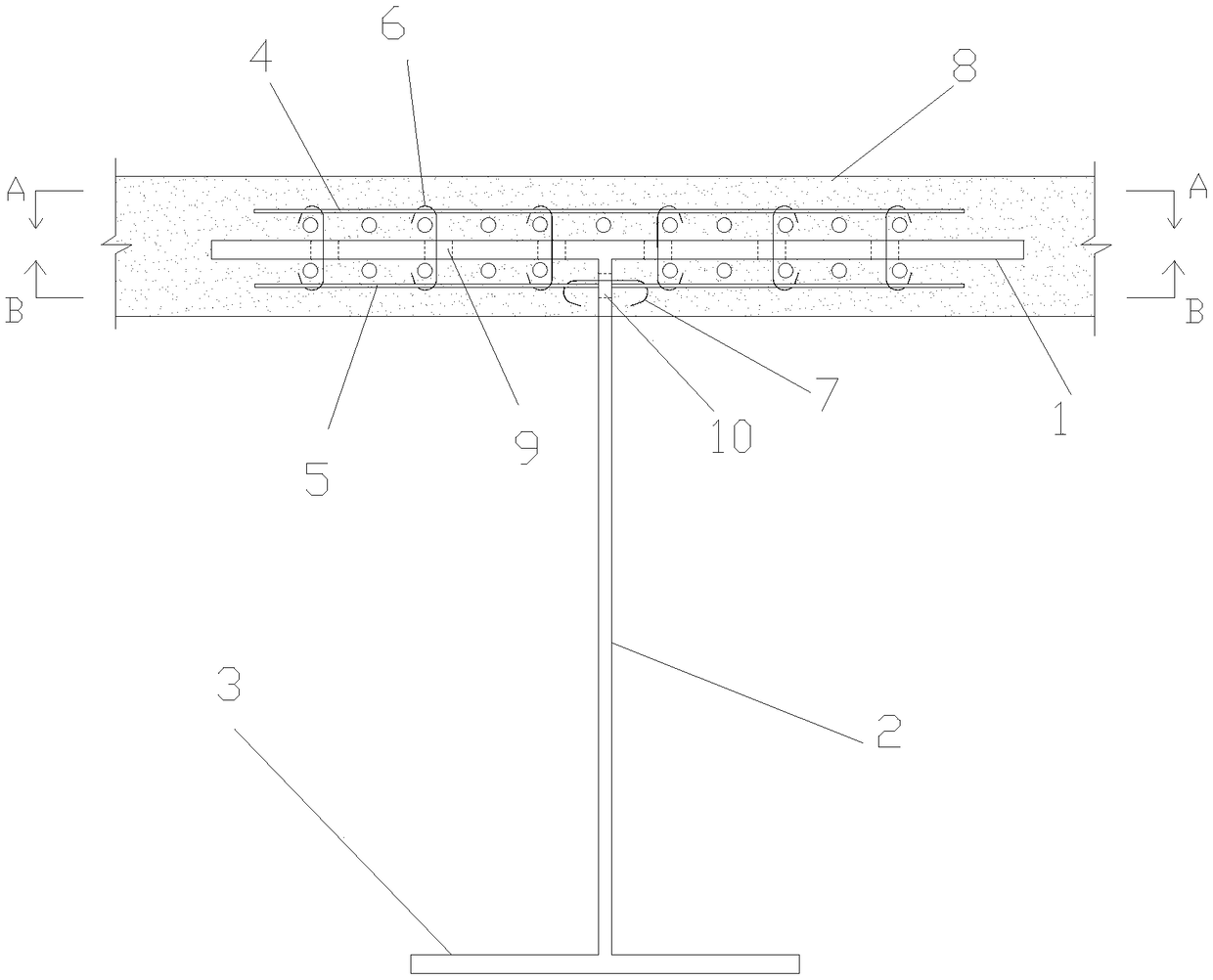
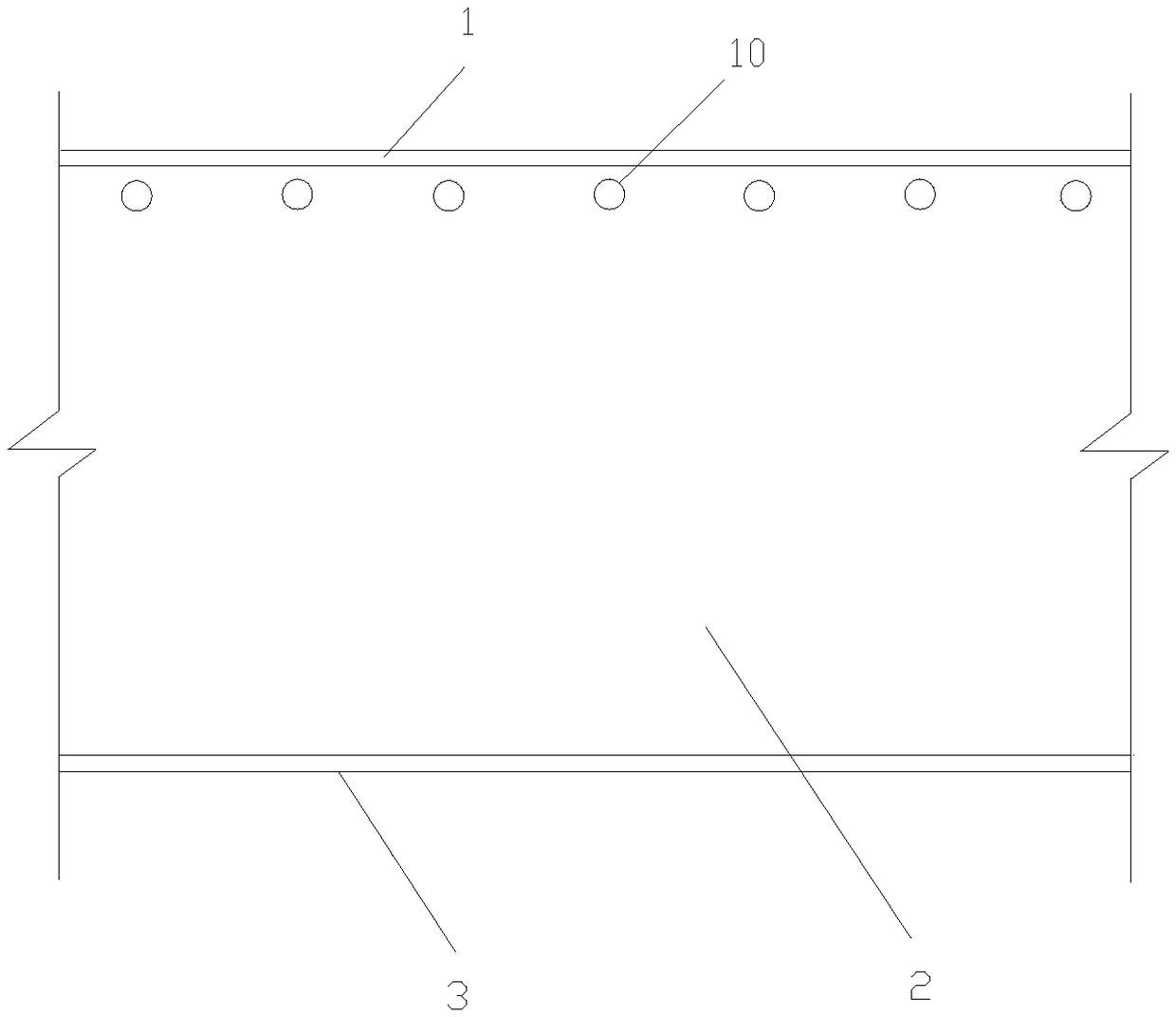
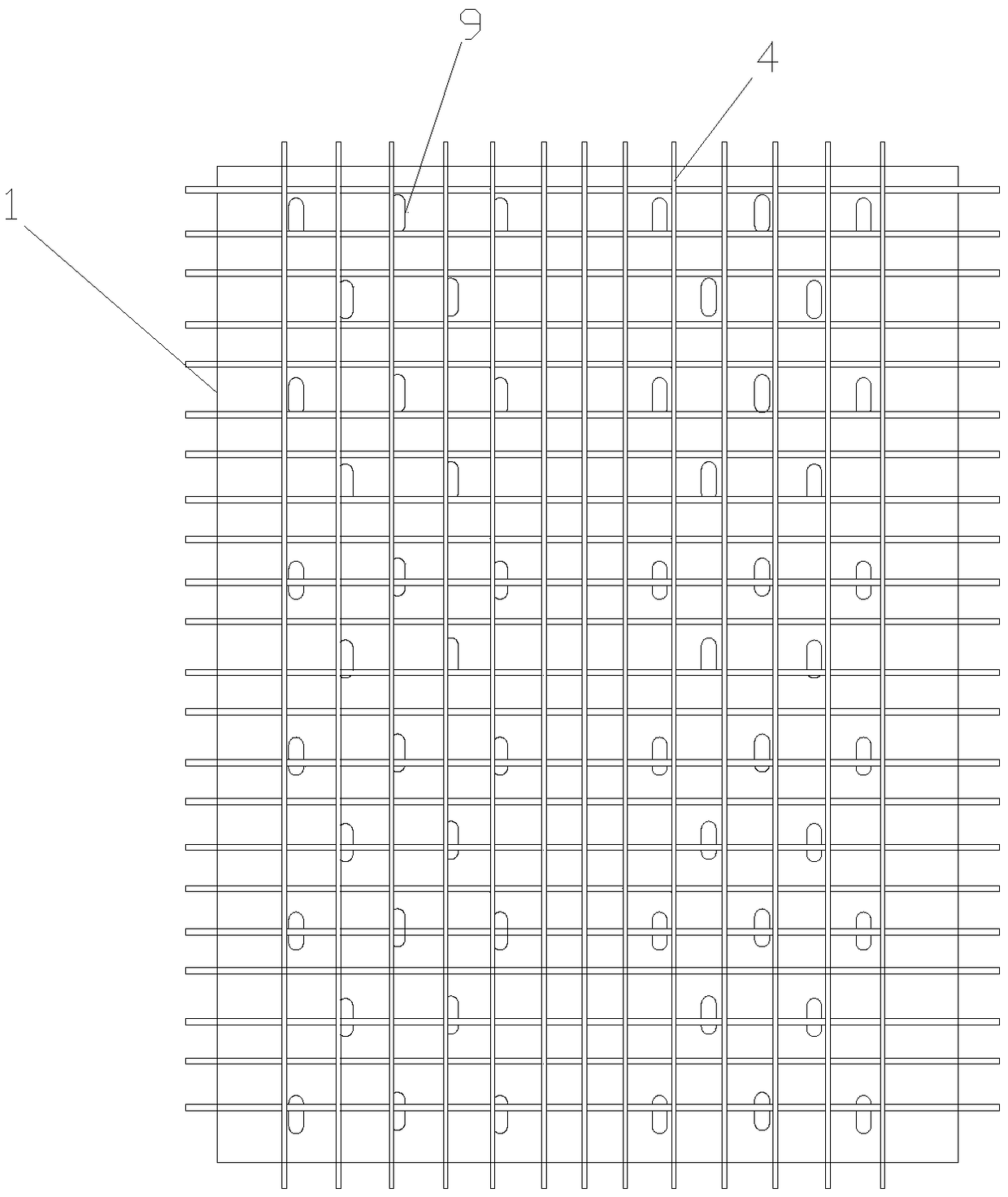
[0062] Such as Figure 1 to Figure 4 The shown steel-concrete composite beam without welded connectors includes a plurality of bridge segments arranged from front to back along the longitudinal direction of the bridge. The structures of the plurality of bridge segments are the same, and each of the bridge segments Each bridge segment includes a steel girder structure arranged on the pier of the constructed bridge, a reinforcement mesh mechanism arranged on the steel girder structure, and a UHPC bridge deck 8 arranged on the steel girder structure and the reinforcement mesh mechanism;

[0063] The steel beam structure includes a bottom plate 3, a top plate 1 and a web 2 connected between the bottom plate 3 and the top plate 1, the steel mesh mechanism is arranged on the top plate 1, and the steel mesh mechanism and the top plate 1 both extend to the In the UHPC bridge deck 8, the reinforcement mesh mechanism includes an upper reinforcement mesh mechanism and a lower reinforceme...


PUM


Abstract

The invention discloses a non-welding connector steel-concrete composite girder and a construction method thereof. The steel-concrete composite girder comprises multiple bridge segments, and each bridge segment comprises a steel girder structure, a steel mesh mechanism and a UHPC bridge deck arranged on the steel girder structure, wherein the steel girder structure comprises a base plate, a top plate and a web; the steel mesh mechanisms are arranged on the upper sides and the lower sides of the steel girder top plates and connected through vertical reinforcements penetrating through the steelgirder top plates, and the steel girder top plates, the steel mesh mechanisms and the vertical reinforcements are all wrapped by the UHPC bridge decks. The construction method for the construction process of each bridge segment comprises the following steps of 1, steel girder structure installation; 2, steel mesh mechanism installation; 3, UHPC bridge deck formation; 4, all construction process performing by repeating the steps from first to third multiple times. Accordingly, by means of the vertical reinforcements, shearing force between the bridge decks and the steel girder top plates is transmitted, people do not need to weld shearing force connectors to the top plates, construction is simplified, and environmental protection is facilitated.

Description

technical field [0001] The invention belongs to the technical field of bridge construction, and in particular relates to a steel-concrete composite beam without welded connectors and a construction method thereof. Background technique [0002] Steel girder is a high-performance building material with high tensile and compressive strength. The compressive strength of concrete is much greater than its tensile strength, and its cost is lower than that of steel girder. Steel-concrete composite girders are equipped with concrete bridge decks on top of steel girders. , the concrete bridge deck and the steel girder are connected together by shear members to bear the force together. In the same section, the concrete bridge deck is under compression and the steel girder is under tension, which can give full play to the material properties of concrete and steel girder, and the mechanical properties are better. [0003] The traditional composite beam connects the concrete bridge deck ...

Claims


Application Information

Patent Timeline
Patent Type & Authority Applications(China)
IPC IPC(8): E01D21/00E01D19/00E01D19/12E01D101/24E01D101/30
CPCE01D19/00E01D19/125E01D21/00E01D2101/30E01D2101/24Y02A30/30
Inventor 柴生波胡勇张云龙张瑞琳
Owner XIAN UNIV OF SCI & TECH
Why Eureka
Try Eureka