A Method of Automatically Generating Pipe and Instrument Flow Chart

A technology of automatic generation and flow chart, applied in the direction of instruments, special data processing applications, electrical digital data processing, etc., can solve problems such as tediousness, affecting work, and heavy workload

Active Publication Date: 2016-07-06
BC P INC CHINA NAT PETROLEUM CORP +1
View PDF3 Cites 0 Cited by
  • Summary
  • Abstract
  • Description
  • Claims
  • Application Information

AI Technical Summary

Problems solved by technology

[0007] (2) Due to the huge workload and tediousness, there are often design quality problems such as repeated, missing, and errors in the designation number, which may affect the work of related professions in small cases, and affect the implementation of quotation, procurement, and construction in large cases

Method used


Image

  • A Method of Automatically Generating Pipe and Instrument Flow Chart
  • A Method of Automatically Generating Pipe and Instrument Flow Chart

Examples


Embodiment Construction

[0020] The following will clearly and completely describe the technical solutions in the embodiments of the present invention with reference to the accompanying drawings in the embodiments of the present invention. Obviously, the described embodiments are only some, not all, embodiments of the present invention. Based on the embodiments of the present invention, all other embodiments obtained by persons of ordinary skill in the art without making creative efforts belong to the protection scope of the present invention.

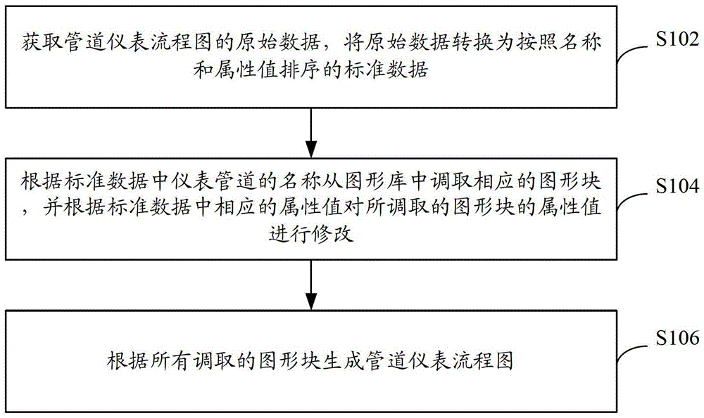
[0021] A complete set of piping and instrument flow charts clearly marks all the requirements of the process flow on the plant installation design, including all equipment, piping, instruments, etc. Content and data. The design of pipeline instrument flow chart specifically includes the following contents.

[0022] 1. Equipment, specifically including:

[0023] (1) The name and tag number of the device. Every piece of equipment, including spare equipment, mu...


PUM


Abstract

The invention discloses a method for automatically generating a pipeline meter flow diagram. The method comprises the following steps that original data of the pipeline meter flow diagram are acquired and converted into standard data ordered according to names and attribute values; corresponding graph blocks are retrieved from a graphic base according to the names of pipeline meters in the standard data, and attribute values of the retrieved graph blocks are modified according to corresponding attribute values in the standard data, wherein the graphic base is established in advance according to the categories of the pipeline meters. The categories of the pipeline meters comprise meter bodies, pipelines and devices. The graph blocks in the graphic base are categorized according to the meter bodies, the pipelines and the devices. Each graph block comprises the name and the attribution value of a corresponding pipeline meter. The pipeline meter flow diagram is generated according to all the retrieved graph blocks.

Description

technical field [0001] The invention relates to the field of chemical instruments, in particular to a method for automatically generating a pipeline instrument flow chart. Background technique [0002] Innovating working methods and improving technical means are shortcuts to improve work efficiency and work quality with low input and high output. P&ID (ProcessandInstrumentDiagram, flow chart of pipeline instrumentation) utilizes uniformly stipulated graphic symbols and text codes to map all the equipment, instruments, pipelines, valves and main pipe fittings required for the establishment of chemical process equipment according to their respective functions and processes. The requirements are combined to play the role of describing the structure and function of the process equipment. The design of P&ID is completed on the basis of PFD (ProcessFlowDiagram, process material balance diagram). P&ID is the basis for professional design of process, instrumentation, piping and eq...

Claims


Application Information

Patent Timeline
Patent Type & Authority Patents(China)
IPC IPC(8): G06F17/50
Inventor 赵猛裴红郑永新谢加才赵文学潘艳华李阅明
Owner BC P INC CHINA NAT PETROLEUM CORP
Why Eureka
Try Eureka