
Full-automatic slot incoming machine for storage battery plate pack

A pole group and battery technology, applied in the field of automatic battery combination pole group slotting machine, can solve the problems of lead dust, low production efficiency, large human factors, etc., to reduce labor costs, improve efficiency, Avoid inefficient effects

Active Publication Date: 2013-08-21
FUJIAN JIANYANG YAHENG MACHINERY MFG
View PDF4 Cites 23 Cited by
  • Summary
  • Abstract
  • Description
  • Claims
  • Application Information

AI Technical Summary

Problems solved by technology

[0002] In the battery assembly process, loading the combined pole group into the battery slot is a key process to ensure that no waste products are assembled in the battery. This process must be loaded into the combined pole group according to the specified position and direction of each single battery in the battery pack. In order to ensure that they are connected in series to form a battery pack with rated voltage and correct terminal polarity, at present, manual operation is the main method, and human factors are large, and it is affected by factors such as the operator's emotion and technology, and lead dust is very harmful to the operator's body , serious environmental pollution and low production efficiency, therefore, the full automation of battery combination electrode group into the tank is the key technology of battery production, which is of great significance to improve production efficiency and reduce personnel hazards

Method used


Image

  • Full-automatic slot incoming machine for storage battery plate pack
  • Full-automatic slot incoming machine for storage battery plate pack
  • Full-automatic slot incoming machine for storage battery plate pack

Examples


Embodiment Construction

[0032] The embodiments of the present invention are described in detail below: the present embodiment is implemented under the premise of the technical solution of the present invention, and detailed implementation and specific operation process are provided, but the protection scope of the present invention is not limited to the following implementation example.

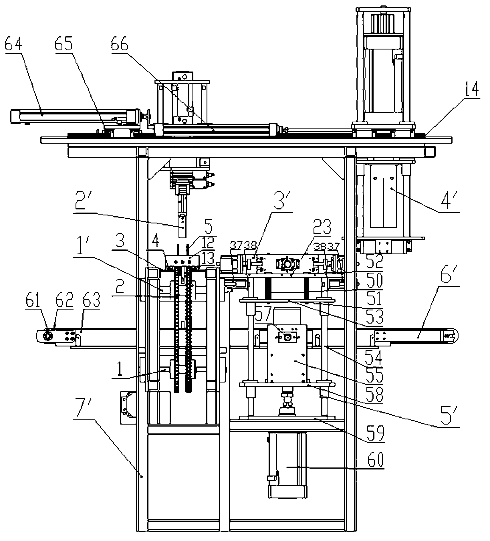
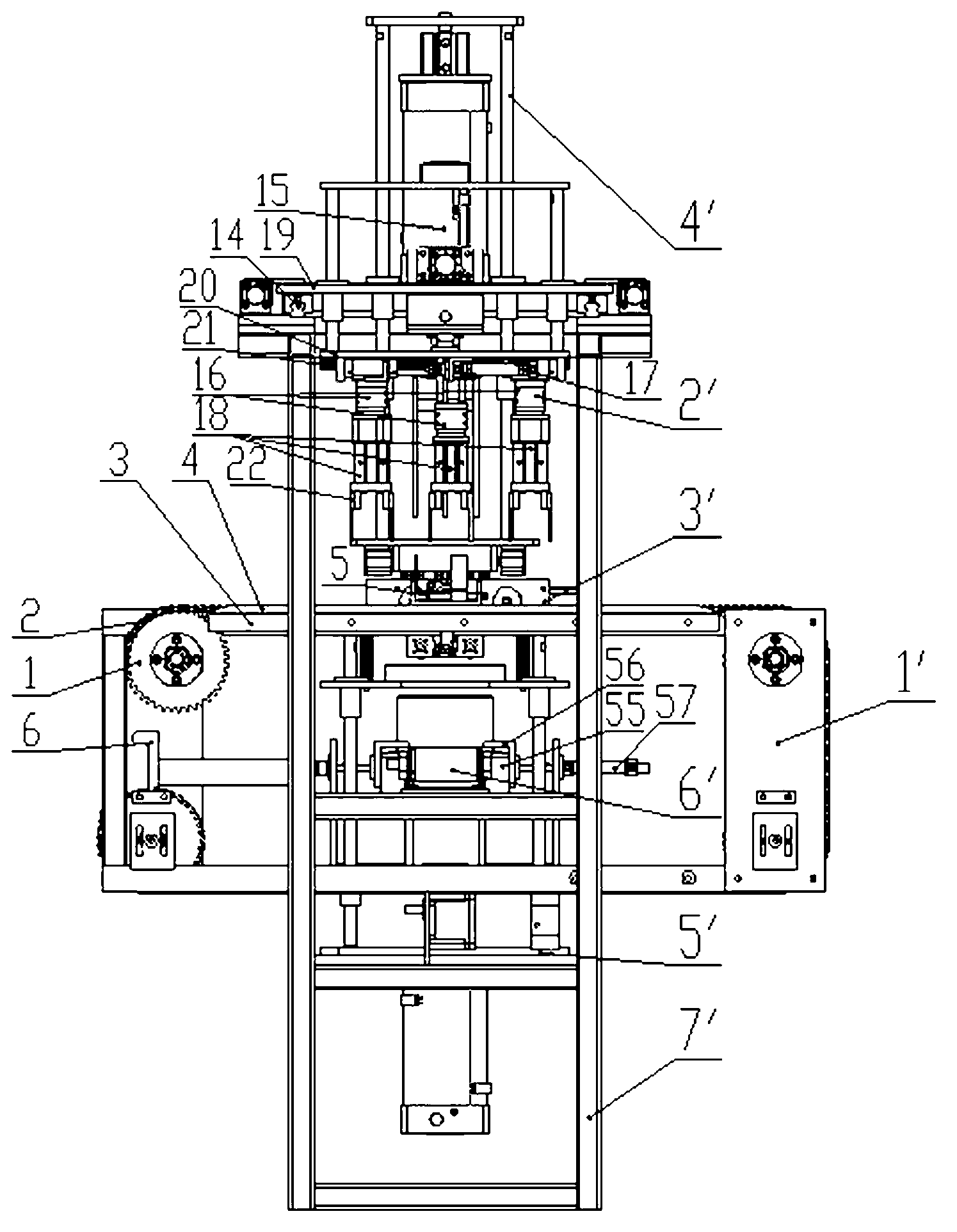
[0033] Such as figure 1 and figure 2 As shown, this embodiment includes: a material receiving and erecting mechanism 1' for realizing material receiving and erecting pole groups, a manipulator mechanism 2' for simultaneously grasping and placing several sets of pole groups, and a shaping mechanism for combining pole groups 3', the assembly mechanism for realizing the tab shaping of the combined pole group and loading into the box groove 4', the battery box jacking mechanism 5', the battery box output mechanism 6', and the frame for carrying the above mechanisms 7' . Wherein, the erecting mechanism 1' for connect...


PUM


Abstract

The invention discloses a full-automatic slot incoming machine for a storage battery plate pack. The full-automatic slot incoming machine comprises a material receiving erecting mechanism, a mechanical arm mechanism, a reshaping mechanism, an equipping mechanism, a battery box jacking mechanism, a battery box output mechanism, a stand and a first guide rail arranged on the stand, wherein the material receiving erecting mechanism is arranged at the inlet of the stand; the reshaping mechanism and the material receiving erecting mechanism are arranged in parallel; the battery box jacking mechanism is arranged just under the reshaping mechanism and is arranged parallel to the material receiving erecting mechanism; the mechanical arm mechanism and the reshaping mechanism are arranged above the material receiving erecting mechanism and on the first guide rail; the output mechanism is arranged in the stand and transversely passes through the interior of the material receiving erecting mechanism and the battery box jacking mechanism. The full-automatic slot incoming machine can complete the working procedures such as material receiving, erecting, grabbing, arranging, reshaping, slot incoming and sending out of the plate pack, so that the production efficiency is greatly improved, and the defects of low in manual slot incoming efficiency, high technical requirement, high in harm of lead dust and the like, and difficultly guarantees technological requirement.

Description

technical field [0001] The invention relates to the technical field of storage battery manufacturing, in particular to a fully automatic storage battery combined electrode group slotting machine. Background technique [0002] In the battery assembly process, loading the combined pole group into the battery slot is a key process to ensure that no waste products are assembled in the battery. This process must be loaded into the combined pole group according to the specified position and direction of each single battery in the battery pack. In order to ensure that they are connected in series to form a battery pack with rated voltage and correct terminal polarity, at present, manual operation is the main method, and human factors are large, and it is affected by factors such as the operator's emotion and technology, and lead dust is very harmful to the operator's body , serious environmental pollution and low production efficiency, therefore, the full automation of the storage ...

Claims


Application Information

Patent Timeline
Patent Type & Authority Applications(China)
IPC IPC(8): H01M10/12H01M10/14
CPCY02E60/10Y02P70/50
Inventor 吴明晖黄友义
Owner FUJIAN JIANYANG YAHENG MACHINERY MFG
Learn More