Internal combustion engine control apparatus
A technology for control devices and internal combustion engines, applied in engine control, fuel injection control, internal combustion piston engines, etc., can solve problems such as insufficient torque, poor acceleration, and inability to further increase internal combustion engine torque, so as to avoid insufficient torque and prevent Accelerate Bad Effects
- Summary
- Abstract
- Description
- Claims
- Application Information
AI Technical Summary
Problems solved by technology
Method used
Image

Examples
Embodiment approach 1
[0054] [Structure of HV system]
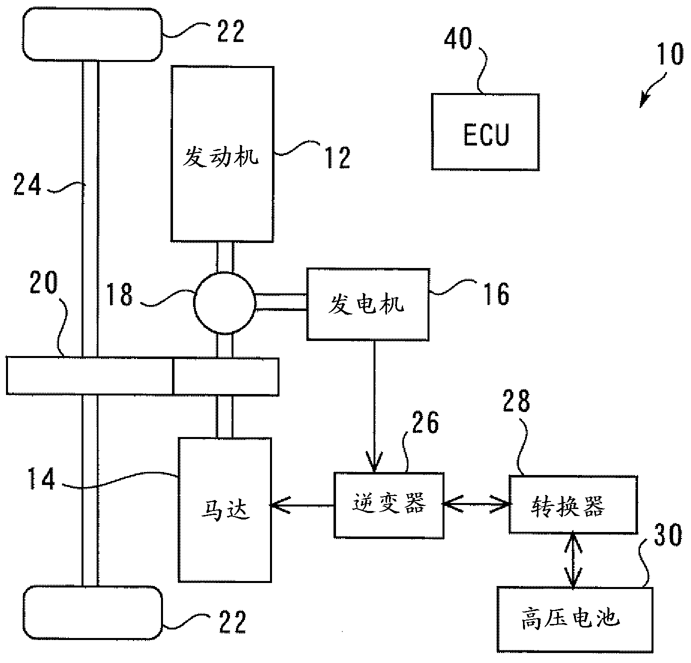
[0055] figure 1 It is a diagram showing a schematic configuration of a drive system 10 of a hybrid vehicle to which the present invention is applied. The drive system 10 includes an internal combustion engine 12 and a vehicle drive motor (hereinafter simply referred to as “motor”) 14 as a second power source of the vehicle. Further, the drive system 10 includes a generator 16 that generates electric power upon receiving supply of driving force. The internal combustion engine 12 , the motor 14 , and the generator 16 are connected to each other via a planetary gear-type power distribution mechanism 18 . A speed reducer 20 is connected to a rotating shaft of the motor 14 connected to the power distribution mechanism 18 . The speed reducer 20 connects the rotation shaft of the motor 14 to a drive shaft 24 , wherein the drive shaft 24 is connected to a drive wheel 22 . The power split mechanism 18 is a device that splits the driving force of t...
Embodiment approach 2
[0089]Second, refer to Image 6 and Figure 7 Embodiment 2 of the present invention will be described.
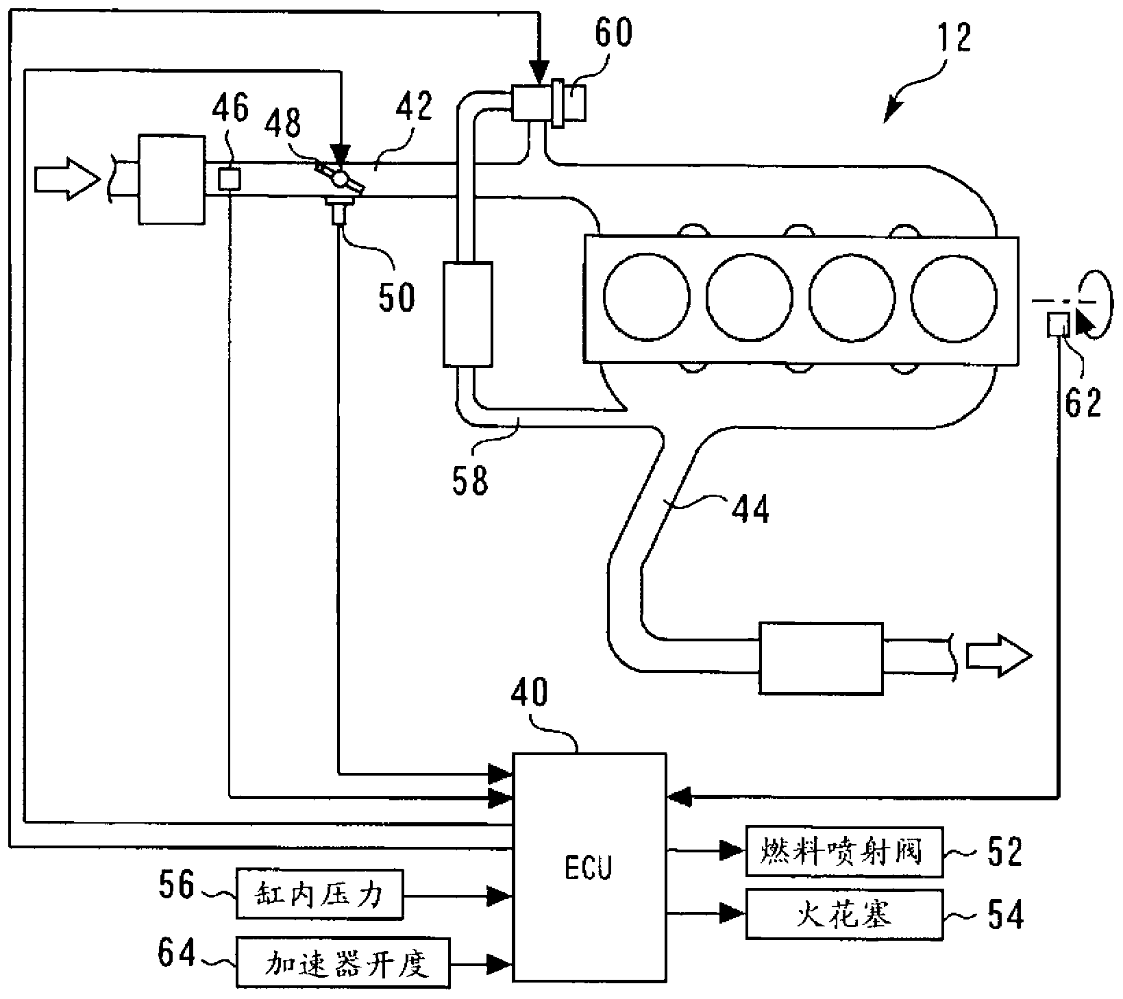
[0090] The system of this embodiment can adopt figure 1 and figure 2 Shown hardware structure, and make ECU 40 carry out the Figure 7 shown in the program to replace the Figure 5 shown in the program to achieve.
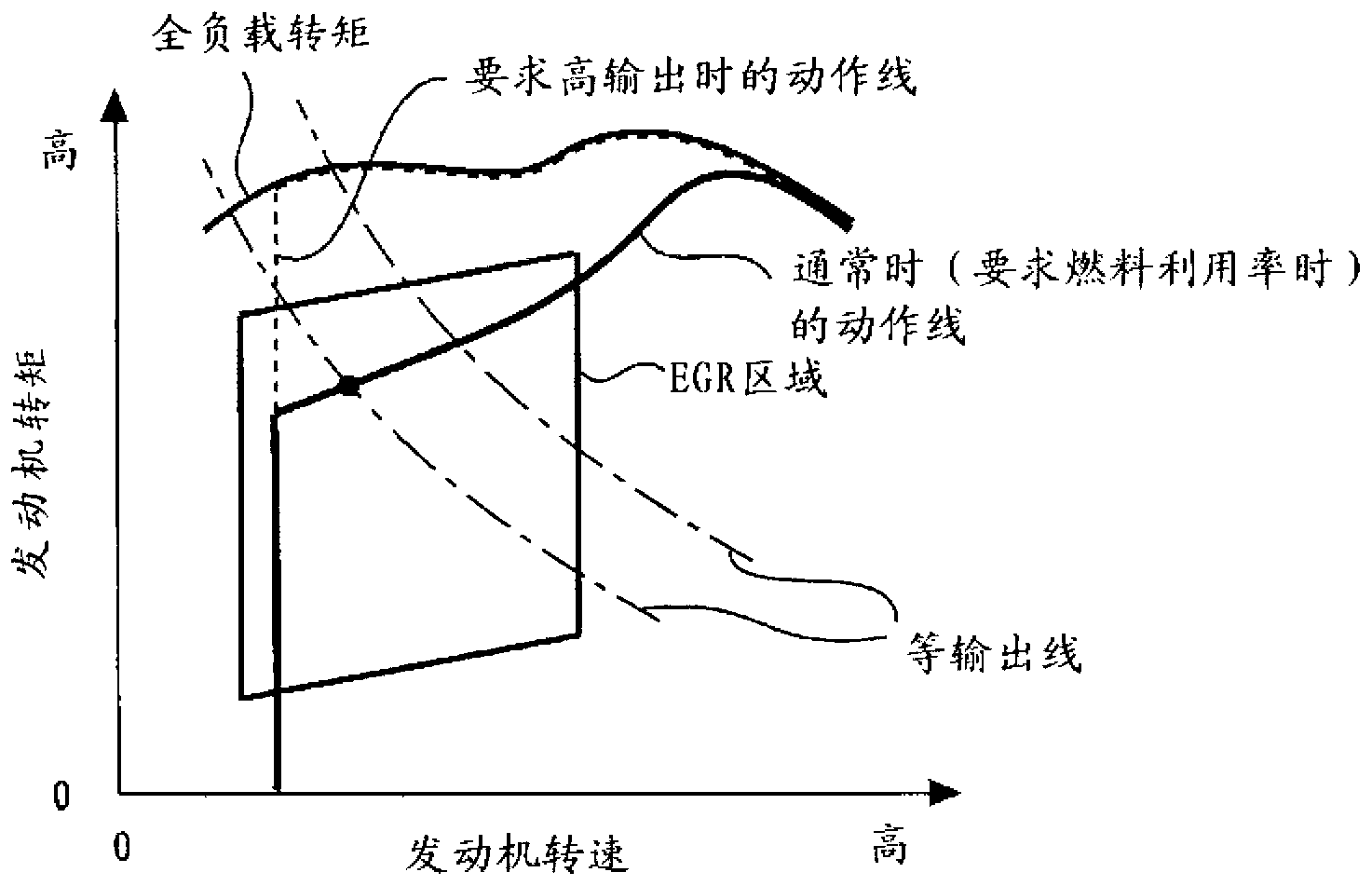
[0091] Image 6 It is a diagram for explaining the characteristic setting of the required throttle opening TAreq according to Embodiment 2 of the present invention.
[0092] In the above-mentioned first embodiment, in order to avoid insufficient torque due to the influence of a large amount of EGR gas during acceleration, in the setting region where it can be judged that the current request is accompanied by an increase in the required torque, the required throttle opening is reduced. In the case of the requested torque, the actual torque of the internal combustion engine 12 is limited to the current torque TQreq with the requested EGR opening EGRreq ca...
Embodiment approach 3
[0106] Second, refer to Figure 8 and Figure 9 Embodiment 3 of the present invention will be described.
[0107] The system of this embodiment can adopt figure 1 and figure 2 Shown hardware structure, and make ECU 40 carry out the Figure 9 shown in the program to replace the Figure 7 shown in the program to achieve.
[0108] Figure 8 It is a diagram for explaining characteristic control during acceleration according to Embodiment 3 of the present invention.
[0109] Also in the present embodiment, as in the second embodiment described above, when the requested torque TQreq larger than the requested torque TQtamax at the time of the maximum throttle opening TAmax is requested in the EGR region, the requested throttle opening is fixed at Maximum throttle opening TAmax. Hereinafter, the section in which the throttle opening is required to be fixed at the maximum throttle opening TAmax will be referred to as a "required throttle opening fixed section".
[0110] In t...
PUM
 Abstract
Description
Claims
Application Information
 - R&D
- Intellectual Property
- Life Sciences
- Materials
- Tech Scout
- Unparalleled Data Quality
- Higher Quality Content
- 60% Fewer Hallucinations
Browse by: Latest US Patents, China's latest patents, Technical Efficacy Thesaurus, Application Domain, Technology Topic, Popular Technical Reports.
© 2025 PatSnap. All rights reserved.Legal|Privacy policy|Modern Slavery Act Transparency Statement|Sitemap|About US| Contact US: help@patsnap.com