Screw implantation sighting device

A technology of sight and screw, applied in the field of screw implantation sight, can solve the problem of high price of computer aided facilities, and achieve the effects of simple structure, firm fixation, and avoidance of shaking

Inactive Publication Date: 2013-08-28
张英泽
View PDF2 Cites 2 Cited by
  • Summary
  • Abstract
  • Description
  • Claims
  • Application Information

AI Technical Summary

Problems solved by technology

[0006] In order to solve the problem of high price of computer-aided facilities in t

Method used


Image

  • Screw implantation sighting device
  • Screw implantation sighting device
  • Screw implantation sighting device

Examples


Embodiment

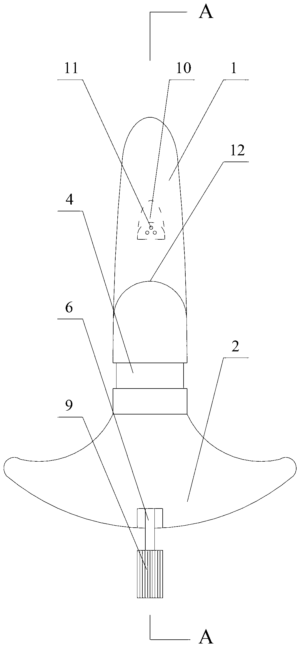
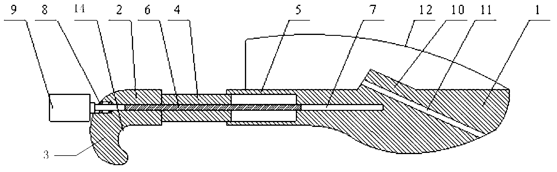
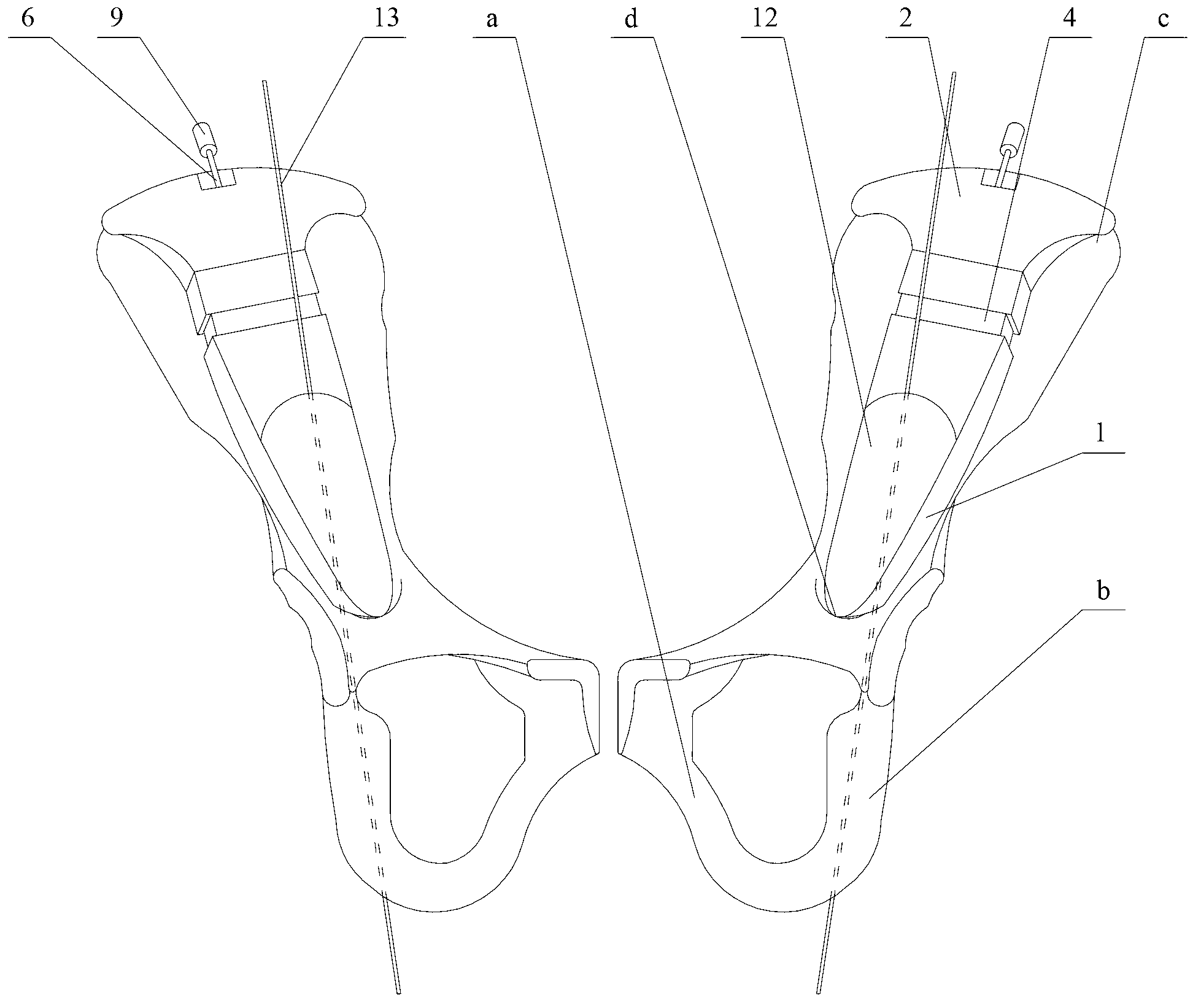
[0024] The present invention provides a screw implantation sight, such as figure 1 with image 3 As shown, the sight includes: the front section 1 of the sight and the rear section 2 of the sight. There are several positioning through holes on the front section 1 of the sight. When the front and bottom surface of the front section 1 of the sight fits with the small pelvis edge, the extension line of the positioning through hole is located in the posterior column of the acetabulum. The rear portion of the rear section 2 of the sight is provided with an arc-shaped limiting plate 3, which is bent from the rear of the rear section 2 of the sight to the bottom surface of the rear section 2 of the sight, and the arc-shaped limiting plate 3 14 of the inner arc (see figure 2 ) radian fits the outer edge of the anterior superior iliac spine c, where the front part of the front section 1 of the aimer bears against the pelvic rim d, which is the first positioning point, and the inner ...


PUM


Abstract

The invention discloses a screw implantation sighting device and belongs to the field of orthopedics department medical instruments. The screw implantation sighting device comprises a sighting device front section and a sighting device back section, the back portion of the sighting device front section is movably connected with the front portion of the sighting device back section, the front portion and the bottom face of the sighting device front section are matched with the edge of the small pelvis, and a plurality of locating through holes are formed in the sighting device front section. When the front portion and the bottom face of the sighting device front section are adhered to the edge of the small pelvis, an extension line of the locating through holes is located in an acetabulum posterior column, an arc-shaped limiting plate is arranged on the back portion of the sighting device back section, the arc-shaped limiting plate is formed by bending of the back portion of the sighting device back section towards the bottom face of the sighting device back section, and the radian of an inner arc of the arc-shaped limiting plate is matched with the upper edge of the anterior superior spine. The screw implantation sighting device is simple in structure and low in cost and has the advantages of being accurate in locating and convenient to operate due to the adoption of multipoint locating and fixing.

Description

technical field [0001] The invention relates to the field of orthopedic medical instruments, in particular to a screw implantation collimator. Background technique [0002] The acetabulum is located in the middle and lower part of the lateral surface of the hip bone. It is composed of the iliac body, the ischial body and the pubic body. For severe fractures, acetabular fractures are generally caused by relatively large impact forces on the acetabulum. Therefore, acetabular fractures are usually accompanied by simultaneous damage to the anterior acetabular column and the posterior acetabular column. Due to the deep position of the acetabulum and complex anatomy , reduction and fixation difficulties, many complications and other reasons have always been difficult problems in the field of orthopedics. [0003] At present, for acetabular fractures, fixation screws are generally used to fix the fracture affected area. During the operation, the direction of needle insertion canno...

Claims


Application Information

Patent Timeline
IPC IPC(8): A61B17/90
CPCA61B17/1746
Inventor 张英泽郑占乐
Owner 张英泽
Why Eureka
Try Eureka