
Cylindrical chamfering jig

A cylindrical surface and chamfering technology, applied in the field of fixtures, can solve the problems of difficult assembly of parts, stress concentration of parts, operator injury, etc., and achieve the effect of improving production efficiency

Inactive Publication Date: 2016-03-30
SUZHOU CHUANGFENG PRECISION HARDWARE
View PDF5 Cites 0 Cited by
  • Summary
  • Abstract
  • Description
  • Claims
  • Application Information

AI Technical Summary

Problems solved by technology

[0002] In the machining process, the metal workpiece after cutting will form sharp sharp corners at the hole end of the round hole, the hole end of the square hole, the shaft end, the shaft shoulder, etc. The assembly causes certain difficulties, and it is easy to cause injury to the operator. At the same time, the existence of sharp corners makes the stress of the parts too concentrated, resulting in serious deformation of the subsequent end faces. Therefore, it is necessary to chamfer the sharp corners

Method used


Image

  • Cylindrical chamfering jig

Examples


Embodiment Construction

[0016] In order to enable those skilled in the art to better understand the solution of the present invention, and to make the above-mentioned purpose, features and advantages of the present invention more obvious and understandable, the present invention will be further described in detail below in conjunction with the embodiments and the accompanying drawings of the embodiments.

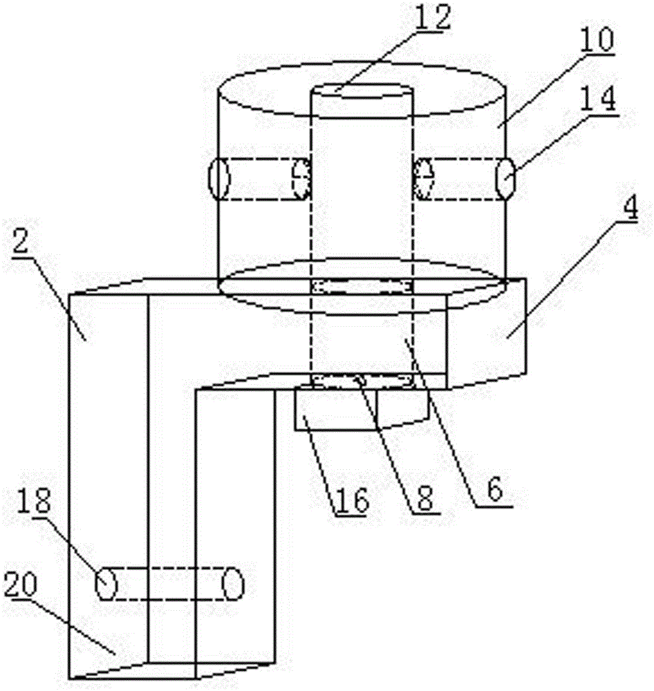
[0017] like figure 1 As shown, a cylindrical surface chamfering jig includes a base 2 with a """ shape in cross section. The base 2 includes a beam 4 and a vertical beam 20 extending vertically along one end of the beam 4. A through hole is opened at the free end of the beam 4. The through groove 6 on the upper and lower surfaces of the crossbeam 4, the external dimensions of the through groove 6 can match the external dimensions of the workpiece to be chamfered, match a kind of through groove 6 for the shape of a workpiece, or the external dimension of the through groove 6 is larger than that of th...


PUM


Abstract

The invention provides a cylindrical surface chamfering fixture which comprises a base of which the section is in a inverted L shape, wherein the base comprises a transverse beam and a vertical beam which vertically extends along one end of the transverse beam; a through groove which penetrates through the upper and lower surfaces of the transverse beam is formed in the free end of the transverse beam; and a chamfering knife is assembled on the lower part of the through groove. The cylindrical surface chamfering fixture is characterized in that a positioning post is arranged on the top of the transverse beam; and a guide shaft hole is formed in the positioning post. According to the cylindrical surface chamfering fixture, the fixture can be rapidly positioned by utilizing a positioning pin on the fixture and an inner hole in the product, the chamfering of the cylindrical surface hole is realized, and the production efficiency is effectively improved; and meanwhile, the machined scraps conveniently drop in the chamfering process, and the phenomenon that the working efficiency is delayed due to the tool blockage is avoided.

Description

technical field [0001] The invention relates to a jig, in particular to a jig suitable for chamfering a cylindrical surface. Background technique [0002] In the machining process, the metal workpiece after cutting will form sharp sharp corners at the hole end of the round hole, the hole end of the square hole, the shaft end, the shaft shoulder, etc. The assembly causes certain difficulties, and it is easy to cause injury to the operator. At the same time, the existence of sharp corners makes the stress of the parts too concentrated, resulting in serious deformation of the subsequent end faces. Therefore, it is necessary to chamfer the sharp corners. Among them, the contour of the hole on the cylindrical surface is the intersecting line of the curved surface. During the processing, the workpiece needs to be absolutely fixed and positioned to improve the processing accuracy. In order to cooperate with the batch processing environment, a cylindrical surface chamfering fixture ...

Claims


Application Information

Patent Timeline
Patent Type & Authority Patents(China)
IPC IPC(8): B23C3/12B23Q3/00
Inventor 徐德明
Owner SUZHOU CHUANGFENG PRECISION HARDWARE
Features
  • Generate Ideas
  • Intellectual Property
  • Life Sciences
  • Materials
  • Tech Scout
  • Unparalleled Data Quality
  • Higher Quality Content
  • 60% Fewer Hallucinations
Learn More