
Hollow floor slab and construction method thereof

A technology of hollow floor slabs and templates, which is applied to floors, building components, buildings, etc., can solve the problems of reducing the strength of iron wires, affecting the life of floor slabs, and rusting of iron wires, and achieves the effects of improving quality, simple structure, and preventing exposure

Inactive Publication Date: 2013-08-28
广东班高得绿色建工科技有限公司
View PDF6 Cites 22 Cited by
  • Summary
  • Abstract
  • Description
  • Claims
  • Application Information

AI Technical Summary

Problems solved by technology

However, when pouring concrete, due to the lighter weight of the lower steel bars and the mandrel, the lower steel bars and the mandrel are prone to float up
In order to solve this technical problem, more technical means are now used to bind the lower steel bars and formwork together with steel wires in advance. After the concrete is poured and solidified, cut the steel wires to remove the formwork. The defects brought about by this method are: formwork After being removed, the steel wire will be exposed outside the floor, and the steel wire will rust after a long time, which will affect the life of the floor
Although this device can solve the deficiencies of the existing problems, when molding the device, a part of the iron wire must be pre-embedded in the base. If the anti-floating device that has been formed is used, the iron wire may also rust, thereby reducing the strength of the iron wire; in addition, the elbow also needs to be pre-embedded into the base during the forming process, so it is very inconvenient to manufacture
[0005] In addition, in the actual construction process, it is found that the distance between the mandrel and the steel bars cannot be limited, and the mandrel is easy to move between the two layers of steel bars, so it brings a lot of inconvenience to the concrete pouring

Method used


Image

  • Hollow floor slab and construction method thereof
  • Hollow floor slab and construction method thereof
  • Hollow floor slab and construction method thereof

Examples


Embodiment Construction

[0052] The present invention will be further described in detail below in conjunction with the accompanying drawings and specific embodiments.

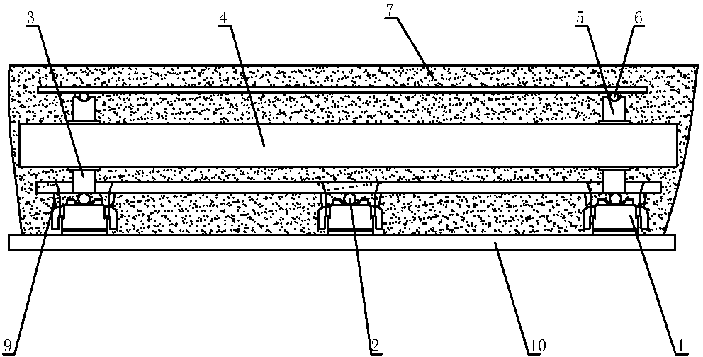
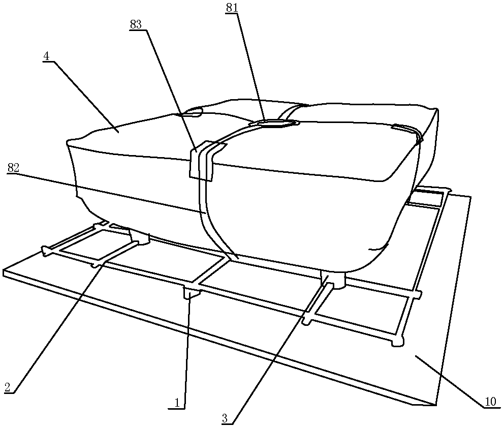
[0053] Such as figure 1 and figure 2 As shown, the hollow floor slab includes anti-floating components 1, protective layer steel bars 2, lower brackets 3, mandrel 4, upper brackets 5, upper steel bars 6, concrete 7 and fixed structures. After the hollow floor slab is formed, the steel bar 2 of the protective layer, the lower support member 3, the mandrel 4, the upper support member 5, and the upper layer steel bar 6 are covered with concrete.

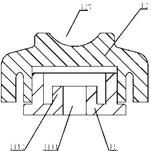
[0054] Such as image 3 As shown, the anti-floating member includes an anti-floating base 11 and an anti-floating upper cover 12 .

[0055] Such as Figure 4 to Figure 7 As shown, the anti-floating base 11 includes a fixed part 111 and a connecting part 112. The cross section of the fixed part 111 and the connecting part 112 is circular, and the lower end of the connecting part 112 is conn...


PUM


Abstract

The invention discloses a hollow floor slab and a construction method of the hollow floor slab. The hollow floor slab comprises an anti-floating component, a protecting layer steel bar, a lower supporting fixing member, a core die, an upper supporting fixing member, an upper layer steel bar, a fixing structure and concrete. The construction method comprises the steps of setting up a formwork, mounting the anti-floating component, laying the protecting layer steel bar, arranging the lower supporting fixing member, mounting the core die, mounting the upper supporting fixing member, laying the upper layer steel bar, pouring the concrete and disassembling the formwork. The hollow floor slab structure is free of the phenomenon that binding iron wires are exposed outwards, and the position of the core die is determined so that the distance among the steel bars and the core die can be limited. The construction method can prevent the steel bars and the core die from floating upwards, the distance among the steel bars and the core die can be limited, the fact that the thickness of the floor slab reaches design requirements is ensured, and meanwhile the binding iron wires can be prevented from being exposed outwards under the premise that the formwork is convenient to disassemble.

Description

technical field [0001] The invention relates to the field of construction, in particular to the structure of a hollow floor slab and its construction method. Background technique [0002] In the past, most of the buildings in our country were reinforced concrete structures. This kind of structure consumes a lot of building materials and is heavy. Especially for the floor slab, the middle part is generally suspended, so the strength of the floor slab is low. For this reason, the country advocates the use of cast-in-place hollow slab technology to realize the construction of the slab. In this way, not only can the consumption materials be reduced, but also the weight of the slab can be reduced. [0003] At present, the technology of adopting cast-in-place hollow-core slabs is mainly as follows: first build the formwork, then lay the lower steel bars on the formwork, fix the mandrel on the lower steel bars, then set the upper steel bars on the mandrel, and finally pour concrete...

Claims


Application Information

Patent Timeline
IPC IPC(8): E04B5/36
Inventor 谭泽文
Owner 广东班高得绿色建工科技有限公司
Learn More